Multi-tenant Azure Site Recovery E2A using Virtual Machine Manager

Azure Site Recovery (ASR) is simple, automated protection and disaster recovery service delivered from the cloud. It enables replication and failover of workloads between datacenters, and from on-premises to Azure. ASR supports physical machines, VMWare and Hyper-V environments. ASR integrates with Windows Azure Pack (WAP) enabling service providers to offer managed disaster recovery for IaaS workloads through the Cloud Solution Provider (CSP) program. I’ll run through configuring ASR to support your multi-tenant cloud, and point out several important caveats in the configuration.

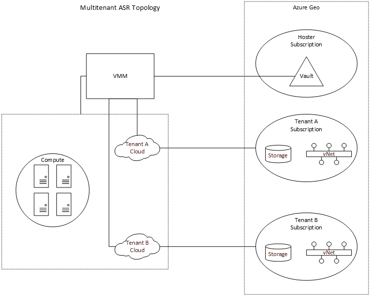
The CSP program enables service providers to resell Microsoft first-party cloud services like Azure, while owning the customer relationship and enabling value-add services. Azure subscriptions provisioned under the CSP program are single-tenant, which presents a challenge when configuring ASR with WAP and Virtual Machine Manager (SCVMM). In order to enable ASR, you must first register a SCVMM server with a Recovery Services vault within an Azure subscription. This will allow ASR to query the SCVMM server and retrieve metadata such as names of virtual machines and networks. In most service provider configurations, a single SCVMM server supports multiple tenants, and as such, you need to register SCVMM to a “master” vault in a subscription owned by the service provider. SCVMM can only be registered to a single vault, which also means that if you are using Azure as a DR target, you can only fail VM’s to a single Azure region. While the SCVMM server can only be registered to a single subscription, we can configure per-cloud protection policies specifying compute and storage targets in other subscriptions. This is an important distinction, as it means that the service provider will need to create separate clouds in VMM (and therefore separate plans in WAP) for EACH tenant. This enables a hoster to provide managed disaster recovery for IaaS workloads in a multi-tenant SCVMM environment. The topology is illustrated below.

Multitenant-ASR

While the initial configuration of the Recovery Services vault can now be done in the Azure portal, configuration of ASR to support multi-tenancy requires using powershell. You’ll need at least version 0.8.10 of Azure Powershell, but I recommend using Web Platform Installer to get the latest.

First,  if you are using the Recovery Services cmdlets for the first time in your subscription, you should register the Azure provider for Recovery Services. Before you can do this, first enable access to the Recovery Services provider on your subscription, by running the following commands. **NOTE: It may take up to an hour to enable access to Recovery Services on your subscription. Attempts to register the provider might fail in the interim.

Register-AzureRmProviderFeature -FeatureName betaAccess -ProviderNamespace Microsoft.RecoveryServices
Register-AzureRmResourceProvider -ProviderNamespace Microsoft.RecoveryServices

Then, let’s setup some constants we’ll use later.

$vaultRgName = "WAPRecoveryGroup"
$location = "westus"
$vaultName = "WAPRecoveryVault"
$vmmCloud = "AcmeCorp Cloud"
$policyName = "AcmeCorp-Policy"
$serverName = "VMM01.contoso.int"
$networkName = "YellowNetwork"
$vmName = "VM01"

Next, connect to your service provider subscription (this can be any direct subscription – EA/Open/PAYG).

$UserName = "user@provider.com"
$Password = "password"
$SecurePassword = ConvertTo-SecureString -AsPlainText $Password -Force
$Cred = New-Object System.Management.Automation.PSCredential -ArgumentList $UserName, $SecurePassword
Login-AzureRmAccount -Credential $Cred

If you have access to multiple subscriptions, you’ll need to set the subscription context.

#Switch to the service provider's subscription
Select-AzureRmSubscription -TenantId 00000000-0000-0000-0000-000000000000 -SubscriptionId 00000000-0000-0000-0000-000000000000

Now we can create the resource group and vault.

#Create the Resource Group for the vault
New-AzureRmResourceGroup -Name $vaultRgName -Location $location
#Create the Recovery Services vault
$vault = New-AzureRmRecoveryServicesVault -Name $vaultName -ResourceGroupName $vaultRgName -Location $location
#Set the vault context
Set-AzureRmSiteRecoveryVaultSettings -ARSVault $vault
#Download vault settings file
Get-AzureRmRecoveryServicesVaultSettingsFile -Vault $vault

At this point, you’ll need to download the Azure Site Recovery provider and run the installation on your SCVMM server, then register the SCVMM server with the vault using the settings file you just downloaded. Additionally, you’ll need to install (but do not configure) the Microsoft Azure Site Recovery agent on each of the Hyper-V servers. Screenshots can be found here.

Now that SCVMM has been registered with the vault, and the agents have been installed, we can create the storage account and virtual network in the tenant subscription.

#Switch to the tenant's subscription
Select-AzureRmSubscription -TenantId 00000000-0000-0000-0000-000000000000 -SubscriptionId 00000000-0000-0000-0000-000000000000
#Storage account must be in the same region as the vault
$storageAccountName = "drstorageacct1"
$tenantRgName =  "AcmeCorpRecoveryGroup" 
#Create the resource group to hold the storage account and virtual network
New-AzureRmResourceGroup -Name $tenantRgName -Location $location
#Create the storage account
$recoveryStorageAccount = New-AzureRmStorageAccount -ResourceGroupName $tenantRgName -Name $storageAccountName -Type "Standard_GRS" -Location $location
#Create the virtual network and subnet
$subnet1 = New-AzureRmVirtualNetworkSubnetConfig -Name "Subnet1" -AddressPrefix "10.0.1.0/24"
$vnet = New-AzureRmVirtualNetwork -Name $networkName -ResourceGroupName $tenantRgName -Location $location -AddressPrefix "10.0.0.0/16" -Subnet $subnet1

We’re ready to create the protection policy and associate it to the SCVMM cloud.

#Switch to the service provider's subscription
Select-AzureRmSubscription -TenantId 00000000-0000-0000-0000-000000000000 -SubscriptionId 00000000-0000-0000-0000-000000000000
#Create the policy referencing the storage account id from the tenant's subscription
$policyResult = New-AzureRmSiteRecoveryPolicy -Name $policyName -ReplicationProvider HyperVReplicaAzure -ReplicationFrequencyInSeconds 900 -RecoveryPoints 1 -ApplicationConsistentSnapshotFrequencyInHours 1 -RecoveryAzureStorageAccountId $recoveryStorageAccount.Id
$policy = Get-AzureRmSiteRecoveryPolicy -FriendlyName $policyname
#Associate the policy with the SCVMM cloud
$container = Get-AzureRmSiteRecoveryProtectionContainer -FriendlyName $vmmCloud
Start-AzureRmSiteRecoveryPolicyAssociationJob -Policy $policy -PrimaryProtectionContainer $container

Once the policy has been associated with the cloud, we can configure network mapping.

#Retrieve the on-premises network
$server = Get-AzureRmSiteRecoveryServer -FriendlyName $serverName
$network = Get-AzureRmSiteRecoveryNetwork -Server $server -FriendlyName $networkName
#Create the network mapping referencing the virtual network in the tenant's subscritpion
New-AzureRmSiteRecoveryNetworkMapping -PrimaryNetwork $network -AzureVMNetworkId $vnet.Id

Lastly, we enable protection on the virtual machine.

#Get the VM metadata
$vm = Get-AzureRmSiteRecoveryProtectionEntity -ProtectionContainer $container -FriendlyName $vmName
#Enable protection. You must specify the storage account again
Set-AzureRmSiteRecoveryProtectionEntity -ProtectionEntity $vm -Protection Enable –Force -Policy $policy -RecoveryAzureStorageAccountId $recoveryStorageAccount.Id

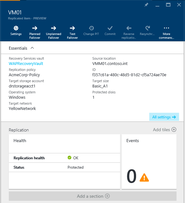
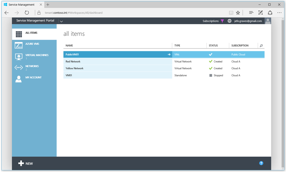
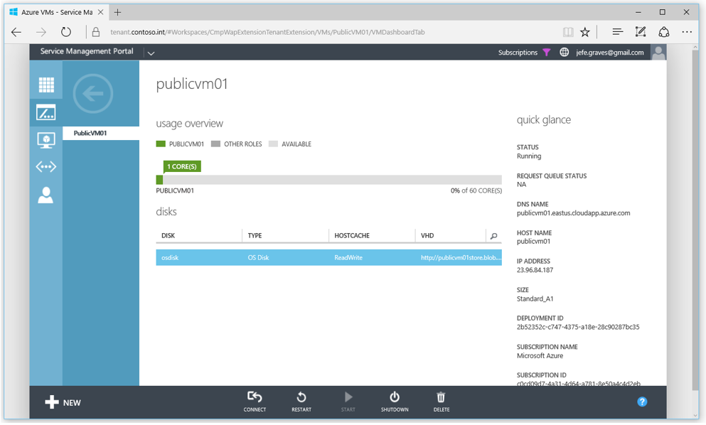
You can monitor protection and perform failovers for a virtual machine in a multi-tenant SCVMM environment to fail over to a tenant’s subscription in Azure from the Recovery Services vault in the provider’s Azure subscription.

Protected-VM01

Azure Pack Connector

In my role as Cloud Technology Strategist with Microsoft over the past 18 months, I’ve been working closely with service providers of all types in making hybrid cloud a reality. Microsoft is uniquely positioned to be able to deliver on the 3 key pillars of cloud – on-premises, hosted, and public – via the Microsoft Cloud Platform. Service providers understand the value of hybrid and, with the release of Azure Pack Connector, have a tool they can use to provide a unified experience for managing public and private cloud.

Azure Pack was released in the fall of 2013 as a free add-on for Windows Server and System Center. It extended the private cloud technology delivered in Virtual Machine Manager to provide self-service multi-tenant Infrastructure as a Service (IaaS) through Hyper-V, in a manner that is consistent with IaaS in public Azure. As more and more enterprises see the value in distributed cloud, service providers are looking to extend their managed services to be able to provision and manage workloads not only running in their data center via Azure Pack, but also IaaS workloads running in public Azure. While Azure Pack ensures the portal and API is consistent, it was still two separate management experiences. Azure Pack Connector bridges that gap by enabling provisioning and management of IaaS in public Azure, through Azure Pack.

Azure Pack Connector

The solution was originally developed by Microsoft IT for internal use to enable various development teams to self-service on public Azure IaaS. Azure Pack Connector was born out of collaboration with the Microsoft Hosting and Cloud Services team to bring the MSIT solution to service providers as open source software released under MIT license. Azure Pack Connector was developed specifically with Cloud Solution Provider partners is in mind, supporting Azure Resource Manager API and including tools to configure Azure subscription provisioned in the CSP portal or CREST API for use with Azure Pack Connector.

The solution consists of 4 main components:

  • Compute Management Service – A windows service that orchestrates the provisioning and de-provisioning of Azure VM’s.
  • Compute Management API – A backend API supporting UI components and enabling management of Azure VM’s.
  • Admin Extension – UI extension for Azure Pack that enables on-boarding and management of Azure subscriptions.
  • Tenant Extension – UI extension for Azure Pack that enables tenant self-service provisioning and management of Azure VM’s.

The Azure Pack Connector subscription model uses a 1-to-1 mapping of Azure Pack plans to Azure Subscriptions, allowing the administrator to control VM operating systems and sizes on a per plan basis and Azure regions globally. Once a user has a subscription to an Azure Pack plan that has an attached Azure subscription, they can provision and manage Azure VM’s through the Azure Pack tenant portal.

Azure Pack Connector Dashboard

This video walkthrough will help explain the features and demonstrate how to use Azure Pack Connector:


The Azure Pack Connector solution is published on GitHub:

https://github.com/Microsoft/Phoenix

Head on over and grab the binaries to expand your Azure Pack installation today!


Automating VMWare to Hyper-V Migrations using MVMC

There are several tools for migrating VMWare VM’s to Hyper-V. The free tool from Microsoft is called the Microsoft Virtual Machine Converter which allows you to convert from VMWare to Hyper-V or Azure, and from physical to virtual via a GUI or powershell cmdlets for automation. Microsoft also has the Migration Automation Toolkit which can help automate this process. If you have NetApp, definitely check out MAT4SHIFT which is by far the fastest and easiest method for converting VMWare VM’s to Hyper-V. MVMC works fairly well, however, there are a few things the tool doesn’t handle natively when converting from VMWare to Hyper-V.

First, it requires credentials to the guest VM to remove the VMWare Tools. In a service provider environment, you may not have access to the guest OS, so this could be an issue. Second, the migration will inherently cause a change in hardware, which in turn can cause the guest OS to lose its network configuration. This script accounts for that by pulling the network configuration from the guest registry and restoring it after the migration. Lastly, MVMC may slightly alter other hardware specifications (dynamic memory, mac address) and this script aims to keep them as close as possible with the exception of disk configuration due to Gen 1 limitations in Hyper-V booting.

This script relies on several 3rd party components:

You’ll need to install MVMC, HV PS Module, and VMWare PowerCLI on your “helper” server – the server where you’ll be running this script which will perform the conversion. Devcon, the HV IS components, VMWare Tools, and NSSM will need to be extracted into the appropriate folders:

vmware-to-hyper-v-folder-structure

I’ve included a sample kick-off script (migrate.ps1) that will perform a migration:

$esxhost = "192.168.0.10"
$username = "root"
$password = ConvertTo-SecureString "p@ssWord1" -AsPlainText -Force
$cred = New-Object -Typename System.Management.Automation.PSCredential -Argumentlist "root", $password
$viserver = @{Server=$esxhost;Credential=$cred}
 
$destloc = "\\sofs.contoso.int\vm-storage1"
 
$vmhost = "HV03"
 
$vmname = "MYSERVER01"
 
cd C:\vmware-to-hyperv-convert
 
. .\vmware-to-hyperv.ps1 -viserver $viserver -VMHost $vmhost -destLoc $destloc -VerboseMode
 
$vms = VMware.VimAutomation.Core\Get-VM -Server $script:viconnection
 
$vmwarevm = $vms | ?{$_.Name -eq $vmname}
 
$vm = Get-VMDetails $vmwarevm
 
Migrate-VMWareVM $vm

Several notes about MVMC and these scripts:

  • This is an offline migration – the VM will be unavailable during the migration. The total amount of downtime depends on the size of the VMDK(s) to be migrated.
  • The script will only migrate a single server. You could wrap this into powershell tasks to migrate several servers simultaneously.
  • Hyper-V Gen1 servers only support booting from IDE. This script will search for the boot disk and attach it to IDE0, all other disks will be attached to a SCSI controller regardless of the source VM disk configuration.
  • Linux VM’s were not in scope as there are not reliable ways to gain write access to LVM volumes on Windows. Tests of CentOS6, Ubuntu12 and Ubuntu14 were successful. CentOS5 required IS components be pre-installed and modifications made to boot configuration. CentOS7 was unsuccessful due to disk configuration. The recommended way of migrating Linux VM’s is to pre-install IS, remove VMWare Tools, and modify boot configuration before migrating.
  • These scripts were tested running from a Server 2012 R2 VM migrating Server 2003 and Server 2012 R2 VM’s – other versions should work but have not been tested.
  • ESXi 5.5+ requires a connection to a vCenter server as storage SDK service is unavailable on the free version.

How DBPM affects guest VM performance

Dell introduced a feature in their 11G servers called demand-based power management (DBPM). Other platforms refer to this feature as “power management” or “power policy” whereby the system adjusts power used by various system components like CPU, RAM, and fans. In today’s green-pc world, it’s a nice idea, but the reality with cloud-based environments is that we are already consolidating systems to fewer physical machines to increase density and power policies often interfere with the resulting performance.

We recently began seeing higher than normal READY times on our VM’s. Ready time refers to the amount of time a process needed CPU time, but had to wait because no processors were available. In the case of virtualization, this means a VM had some work to do, but it could not find sufficient free physical cores that matched the number of vCPU’s assigned to the VM. VMWare has a decent guide for troubleshooting VM performance issues which led to some interesting analysis. Specifically, our overall CPU usage was only around 50%, but some VM’s were seeing ready times of more than 20%.

This high CPU ready with low CPU utilization could be due to several factors. Most commonly in cloud environments, it suggests the ratio of vCPU’s (virtual CPU’s) to pCPU’s (physical CPU’s) is too high, or that you’ve sized your VM’s improperly with too many vCPU’s. One important thing to understand with virtual environments, is that a VM with multiple cores needs to wait for that number of cores to become free across the system. Assuming you have a single host with 4 cores running 4 VM’s, 3 VM’s with 1vCPU and 1 VM with 4vCPU’s, the 3 single vCPU VM’s could be scheduled to run concurrently while the fourth would have to wait for all pCPU’s to become idle.

Naturally, the easiest way to fix this is to add additional physical CPU’s into the fold. We accomplished this by upgrading all of our E5620 processors (4-core) in our ESXi hosts to E5645 processors (6-core) thereby adding 28 additional cores to the platform. However, this did not help with CPU READY times. vSphere DRS was still reporting trouble delivering CPU resources to VM’s:

DRS-before-dbpm

After many hours of troubleshooting, we were finally about to find a solution – disabling DBPM. One of the hosts consistently showed lower CPU ready times even though it had higher density. We were able to find that this node had a different hardware power management policy than the other nodes. You can read more about what this setting does in the Host Power Management whitepaper from VMWare. By default, this policy is automatically set as a result of ACPI CPU C-States, Intel Speedstep and the hardware’s power management settings on the system.

On our Dell Poweredge R610 host systems, the DBPM setting was under Power Management in the BIOS. Once we changed all systems from Active Power Controller to Maximum Performance, CPU ready times dropped to normal levels.

dell-r610-bios-power-management-settings

Information on the various options can be found in this Power and Cooling wiki from Dell. Before settling on this solution, we attempted disabling C-States altogether and C1E specifically in the BIOS, but neither had an impact. We found that we could also specify OS Control for this setting to allow vSphere to set the policy, though we ultimately decided that Maximum Performance was the best setting for our environment. Note that this isn’t specific to vSphere – the power management setting applies equally to all virtualization platforms.

Configure VMM 2012 SP1 Network Virtualization for use with Service Management Portal

With the RTM release of the Service Management Portal from Microsoft, hosters can configure VMM 2012 SP1 to allow self-service tenants to create NVGRE networks for use with VM’s deployed through the portal. The VMM Engineering Blog has a great post that provides a basis for understanding how Network Virtualization is configured in VMM 2012 SP1.

The process can be summarized as follows:

  1. Create a Logical Network with a Network Site & Subnet for use as the Provider Address.
  2. Create an IP Pool on the Logical Network for the Provider Address space.
  3. Create a Host Port Profile linked to the Network Site created in step 1.
  4. Optional: Create a port classification and profile for the virtual adapter. This will allow you to enable DHCP and Router guard on your templates and hardware profiles.
  5. Create the Logical Switch referencing the Host Port Profile (and Virtual Port Classification and Profile if you created them).
  6. Assign the Logical Switch to your Hyper-V hosts.
  7. Assign the Logical Network to your Cloud.
  8. Create a default VM Network for use with templates and hardware profiles.

To create the logical network, in VMM, go to Fabric > Networking > Logical Network and select Create Logical Network from the ribbon menu. Give the network a name (this is what will appear in the Katal portal) and select the “Allow new VM networks created on this logical network to use network virtualization” checkbox, then click Next.Create Logical Network

Add a new network site to be used as the Provider Address network. This is what the Hyper-V hosts will use to communicate with one another.Create Network Site

Now that a Logical Network and Site have been created, we’ll need to create an IP Pool for the Provider Addresses. Right-click on your logical network, and select Create IP Pool. Create IP Pool

Associate the Pool with the Network Site we created in the previous step.Associate Pool with Network Site

You can leave the default range and specify gateway and DNS settings if your Hyper-V hosts span multiple subnets. Next, we’ll want to create a Host Port Profile and associate it with the network site. Right-click Fabric > Networking > Native Port Profiles and select Create Native Port Profile. Name it appropriately and change the type to Uplink port profile.Create Host Port Profile

Associate the Port Profile with the Network Site we created on the Logical Switch and check the checkbox to Enable Windows Network Virtualization. Click Next and Finish.Associate Network Site with Uplink Port Profile

Optionally, you can create a virtual port classification and profile. This will allow you to enable/disable virtual adapter features or create tiers of service. Next, we can create the Logical Switch. From Fabric > Networking > Logical Switches select Create Logical Switch in the ribbon. Give the Switch a name and specify extensions as necessary. Associate the Uplink port profile we created in the previous step.Associate Logical Switch with Uplink Port Profile

Add you virtual port profiles if you created them and then click Finish to create the switch. We’ll now need to associate the switch with our host(s). Find your host under Fabric > Servers > All Hosts > Hostname, right-click and select properties. Click Virtual Switches and then click New Virtual Switch > New Logical Switch. If you have multiple Logical Switches, select the switch we created in the previous step, then select the appropriate adapter(s) and the Uplink Port Profile we created previously. Click OK to assign the logical switch.Assign Switch

Once the job completes, we’ll be able to associate our Logical Network with our cloud which will allow it to show up in the Service Management Portal. Under VMs and Services > Clouds, right-click on the name of your cloud and select Properties. Click Logical Networks, and select the checkbox next to the name of the Logical Network we created in the first step. Click OK.Assign Logical Network


You can now create VM Networks in the Service Management Portal that are bound to the Logical Network using NVGRE.Service Management Portal Create Network

The last step is to create a default VM Network to associate with our templates and hardware profiles. Select VMs and Services > VM Networks and click Create VM Network from the Ribbon. Name the name and associate it with the Logical Network we created in step 1.Create Default VM Network

Chose the option to Isolate using Hyper-V network virtualization with IPv4 addresses for VM and logical networks.Configure NVGRE Isolation

Specify a subnet for VM Network though it will not be used. Select No connectivity on the External connectivity screen and click Finish to create the VM Network. Configure your templates and hardware profiles to use this VM Network in order for them to work properly in the Service Management Portal.

Server 2008 R2 SP1 Hyper-V Dynamic Memory Settings

While working on a recent project for Cytanium Windows VPS Servers, I uncovered a little documented feature that I thought was new for Windows 8 Hyper-V, but was actually implemented in 2008 R2 SP1. It has to do with the minimum and maximum values for VM’s using Dynamic Memory in Hyper-V. The GUI exposes the concept of startup memory and maximum memory, where startup is the amount exposed to the VM while booting as well as the minimum amount of RAM the hypervisor will allocate to the VM, and maximum being the limit the VM will consume.

While working through the WMI API, I stumbled across this:

http://msdn.microsoft.com/en-us/library/cc136856(v=vs.85).aspx

Limit – The maximum amount of memory that may be consumed by the virtual system. For a virtual system with dynamic memory enabled, this represents the maximum memory setting.

Reservation – Specifies the amount of memory guaranteed to be available for this VM. For a virtual system with dynamic memory enabled, this represents the minimum memory setting.

VirtualQuantity – The total amount of RAM in the virtual system, as seen by the guest operating system. For a virtual system with dynamic memory enabled, this represents the initial memory available at startup.

So, there’s actually three settings where VirtualQuantity and Limit map to the startup and maximum values in the GUI. But what about Reservation? This is actually the minimum amount of memory the hypervisor will allocate for a VM. When you configure startup memory in the GUI or via SCVMM, it’s actually setting VirtualQuantity and Reservation to the same values. The reasoning behind this is simple – Microsoft wants to protect you from yourself. By setting the VirtualQuantity to something larger than the Reservation, you could potentially encounter a scenario where a VM reboots, and the host does not have enough memory to satisfy the VM, and has to power down the VM. This is a non-issue in Windows 8 because of Smart Paging.

On the flip side, the value specified in VirtualQuantity is also the amount of memory reported in the VM during boot. So this can cause confusion for some users because the VM may only report the VirtualQuantity on startup, and will always only report the high watermark of RAM allocated – which is typically less than the maximum available to the VM. To prevent this, we can set the VirtualQuantity value to the same as the Limit, and then set the reservation value to the minimum required to run the Operating System. This ensures that the VM always reports the maximum amount of memory available to it, while still allowing the hypervisor to dynamically allocate only what’s necessary to run the workload.

Ben Armstrong has a great post outlining how this can be done via WMI:

http://blogs.msdn.com/b/virtual_pc_guy/archive/2010/09/15/scripting-dynamic-memory-part-5-changing-minimum-memory.aspx

Once you change these values, the GUI actually recognizes the change and warns that modifying the settings will revert to default behavior:

But the actual values behind the scenes:

Limit:                  2048
Reservation:       512
VirtualQuantity:  2048

Shortly after booting, Hyper-V recoups the unused RAM:

But the VM still reports the high watermark:

One potential downside to doing this is that the amount of in-use RAM could be reported incorrectly inside the VM. However, based on my testing, this occurs when using Dynamic Memory via traditional methods as well. The problem is that Windows calculates in use RAM by subtracting available RAM from total RAM. So, for the above VM, the amount of in use RAM is report as ~1.8GB, rather than the ~600MB that’s actually in use by the VM at startup. Do note however, that this occurs anytime a VM is using Dynamic Memory and bursts above the startup value. The VM always reports the high watermark and encounters the same miscalculation of available memory if the memory demand decreases.