The odometer reading for LV Tong LSV’s is stored on the firmware of the instrument cluster. There is currently not a documented way to flash the firmware of the Hefei Huanxin Technology Development Company cluster. However, the odometer is calculated based on the speed sensor signal which can be emulated. By using a signal generator at a high frequency, you can increase the odometer reading of the cluster.
The speed signal is carried on the yellow/green wire connected to pin 1 of J1 on the cluster. Connect the output of a signal generator to this pin (I used the EspoTek Labrador attached to my Surface Go for this) using at least a 3V square wave (the speed sensor on the LSV outputs 12V, but the cluster seems to detect anything over 3V). Be sure your signal generator’s ground is connected to same ground as the power supply otherwise the cluster may not properly detect the signal. The maximum frequency will depend on your specific firmware but the cluster doesn’t seem to be able to process speeds above ~860mph – setting a frequency that generates a speed higher than this doesn’t seem to matter. For mine (580mm tire diameter, 14:1 gear ratio, 4 pulses per rotation) the maximum frequency it could sustain was 13.5kHz (~1000mph).
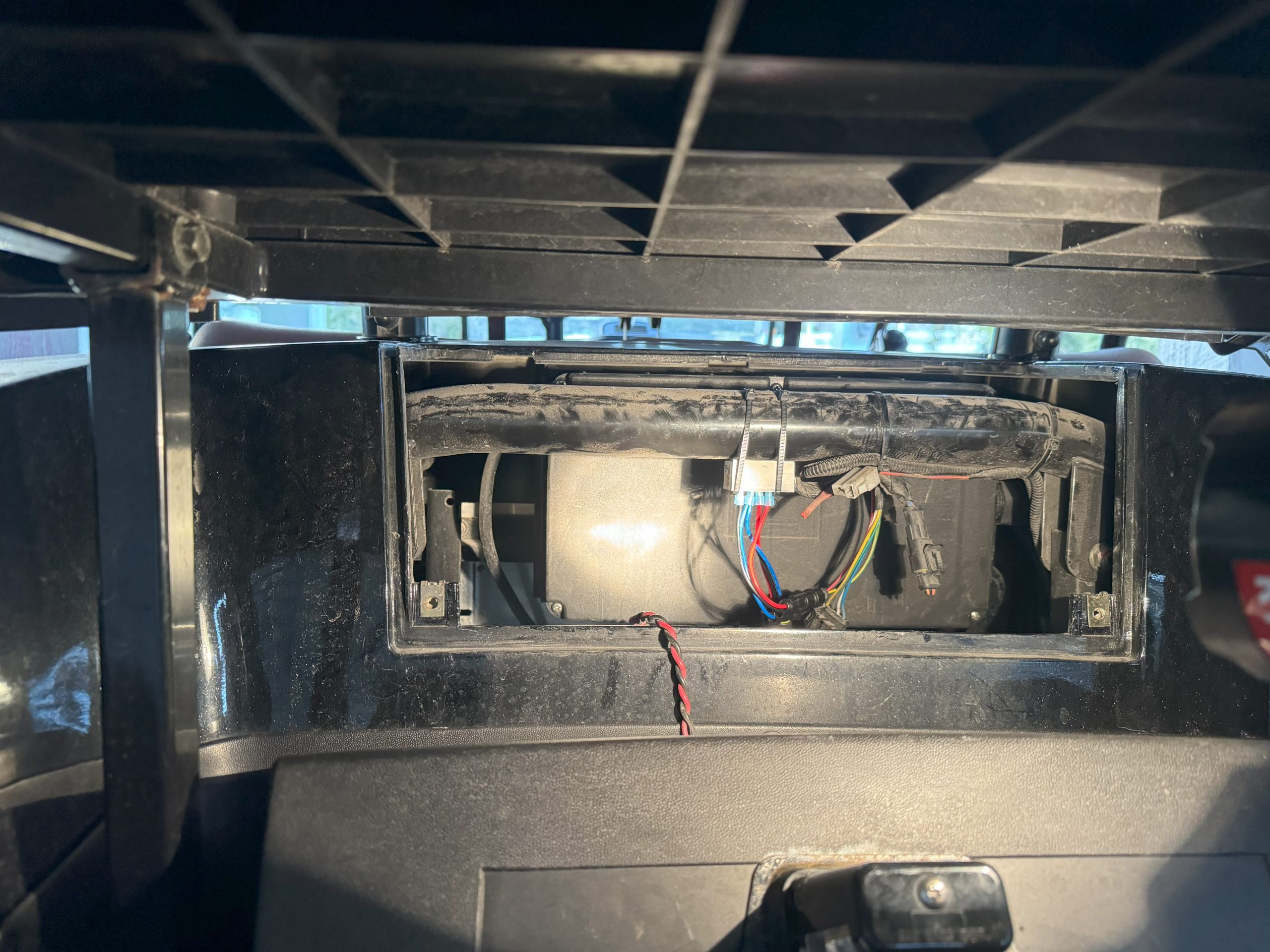
Adding miles to my replacement cluster to match the original odometer reading
Living at the beach has it’s perks – not the least of which is being able to get around on an LSV. We bought an Advanced EV1 6L in December 2021 and couldn’t be happier. We had searched several dealers in the area, but chose the AEV1 given the value and the dealer reputation (shout out to Sun Fun Golf Carts in Carolina Beach). We put over 4000 miles on the cart in the first 2 years on the original lead acid batteries before they started having trouble holding a charge. Since we needed to replace the batteries anyway, I looked into what it would take to upgrade to lithium in October 2022.
Part 1 – Battery Upgrade
I spent quite a while researching various lithium batteries, talked with my neighbor who had an AEV2 with the RoyPow lithium upgrade, and chatted on FB and forums with others who had upgraded. I decided on EcoBattery due to reputation, warranty, and the max continuous discharge. While it’s pretty flat here, we frequently have a full cart and some quick math told me 100A draw wouldn’t be unusual so felt it best to choose something sufficient to handle the load. We got about 14mi of charge (@25mph) from our 170ah lead acid battery bank, so were hoping to increase that slightly and settled on the 144ah bundle (2x 72ah 48V LifePO4) from Elite Custom Golf Carts.
The bundle did not include a busbar or cables and the old ones were too short so I ordered those from Amazon. The 18″ cables were probably a little longer than needed, so you can probably just get 1′ cables. I chose 2awg to given the potential amperage draw:
Installation was fairly simple. The bundle came with an install guide for connecting the batteries in parallel. The stock tray for the lead acid batteries had guides for standard size batteries that needed to be removed with a pair of wire clippers to create a flat area to attach the batteries. The through hole batteries would have been a better fit and allowed me to connect directly to the existing mounts. I mounted the busbar’s in the center, screwed the batteries to the tray and then used lashing straps to ensure the batteries were secured and wouldn’t bounce around. I mounted the new charger in the same place as the previous one and left the stock DC 12V converter.
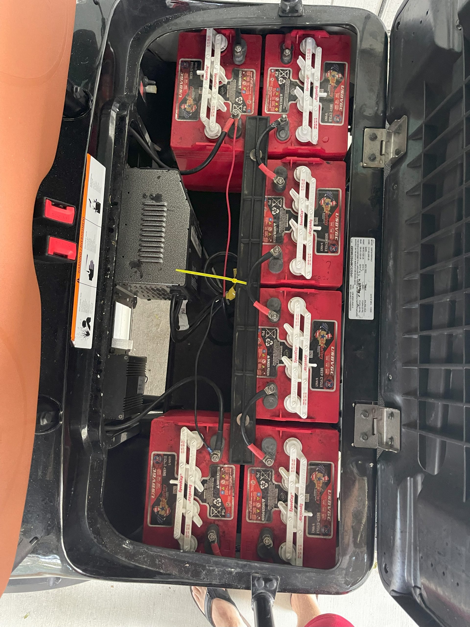
Original configuration with 6x 8V 170ah lead acid batteries from US Battery.
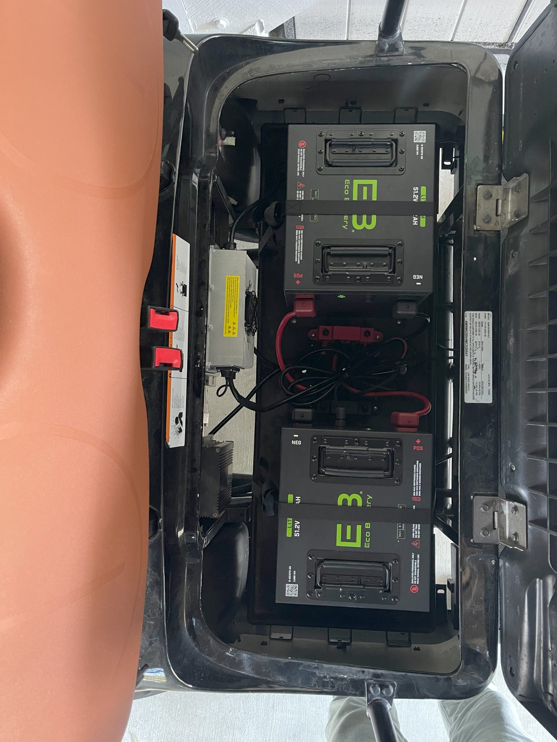
Lithium configuration with 2x 51V 72ah LifePO4 lithium batteries from EcoBattery.
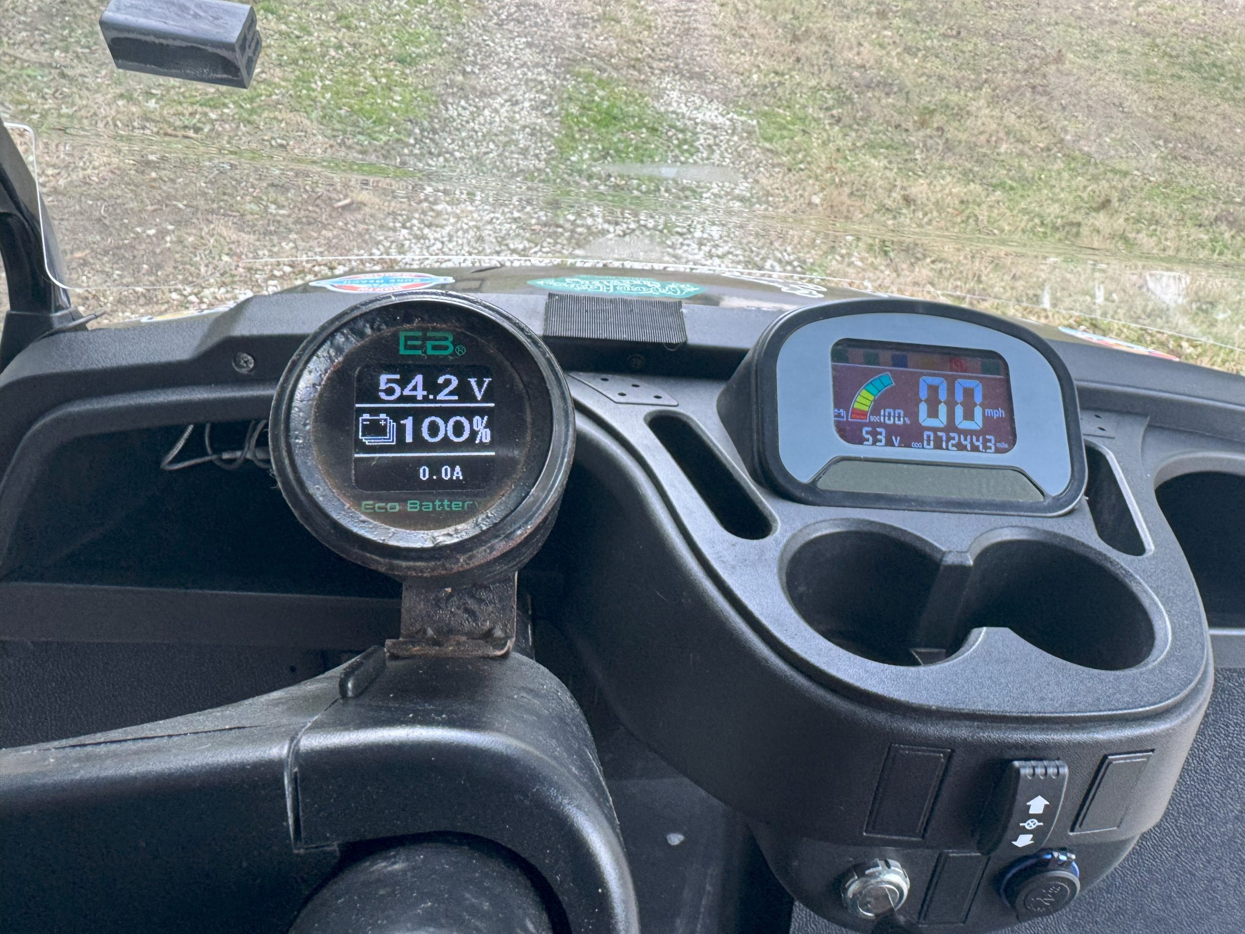
Instead of drilling a hole in the dash for the gauge, I mounted a single gauge metal dashboard pod to the steering column. The gauge connects to a single battery – since they are in parallel, the amount of charge is about the same between the batteries.
*I took this picture about a year after actual install – salt air isn’t kind to exposed metal.
The lithium upgrade was an IMMEDIATE improvement over the lead acid batteries. We extended our useable range to nearly 30mi (@25mph) and have been able to run as low as 15% without any drop in voltage (no more limping home at 12mph). The batteries can get a full charge overnight and with very little self-discharge when the cart sits idle. I’ve also reprogrammed the controller to up the max RPM’s to 6900 and have had no issues with the BMS due to amperage draw.
Part 2 – Upgrade stock cluster
Icon recently announced lithium carts powered by EcoBattery lithium batteries. Given Advanced EV1 and Icon are both LV Tong based LSV’s, I was excited to learn the modified cluster (part # HXYB-FY4800CAN-ECO) EcoBattery has developed in conjunction with Icon can also work with Advanced EV1 carts.
The new cluster adds CAN L (low) and CAN H (high) signals that connect to the existing 5-pin digital battery cable. The kit includes a dongle with female molex pins that are inserted into the existing 20-pin wiring harness – brown is CAN H, blue is CAN L. The steps to install the new cluster are very straight-forward:
Turn off batteries.
Remove the console.
Disconnect the wiring harnesses from the instrument cluster.
Remove the original instrument cluster from the console.
Insert the molex pins from the dongle into the correct spots on the 20-pin harness (brown to CAN H, blue to CAN L).
Install the new instrument cluster into the console.
Connect the 12-pin and 20-pin hardness to the new instrument cluster.
Connect the 4-pin dongle to the 4-pin harness of the digital battery cable.
Replace the console.
Turn on batteries.
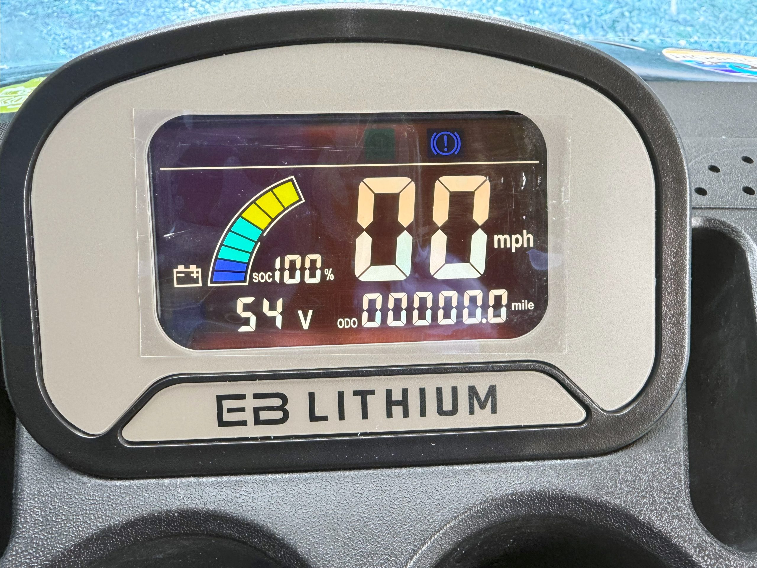
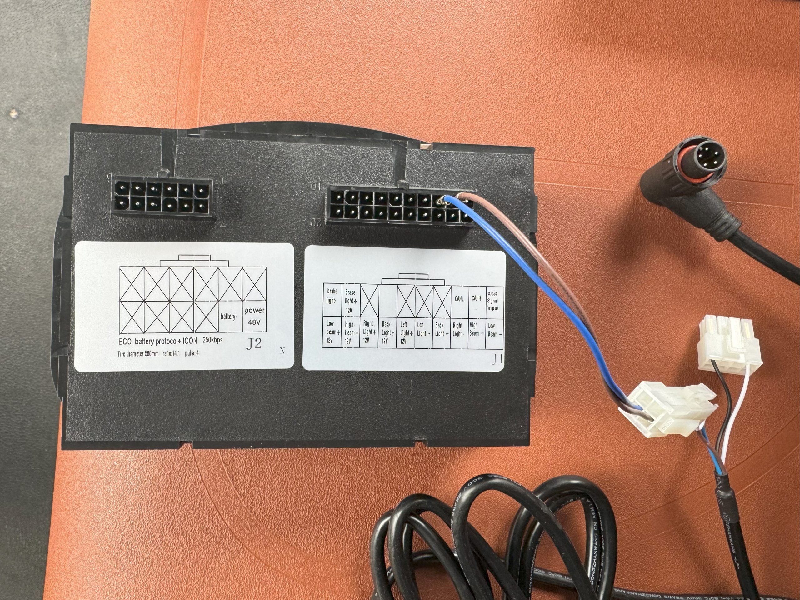
New EcoBattery lithium cluster for LV Tong carts.
Cluster includes pins for CAN L and H to attach dongle.
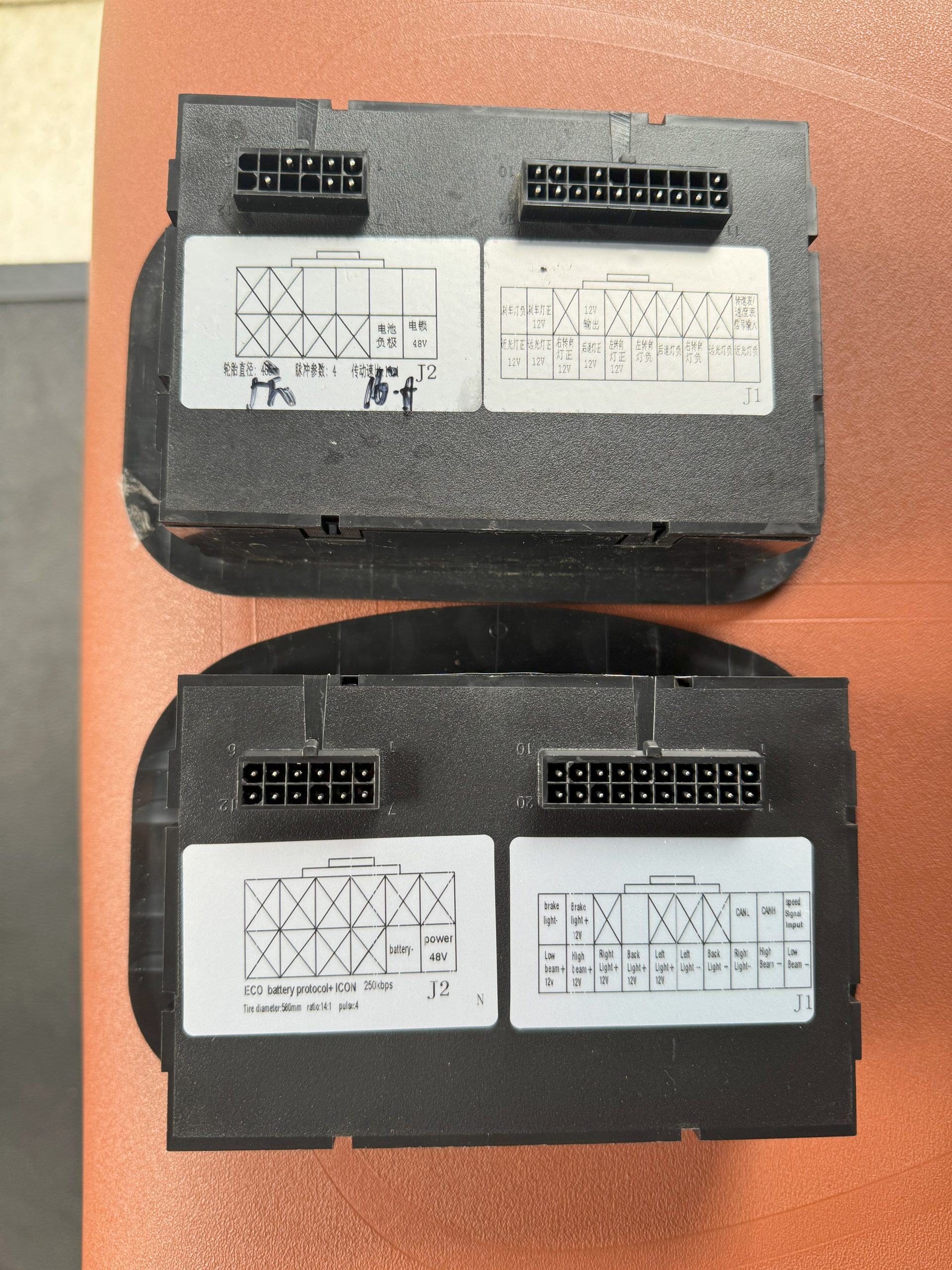
Top: Original cluster, Bottom: EcoBattery cluster.
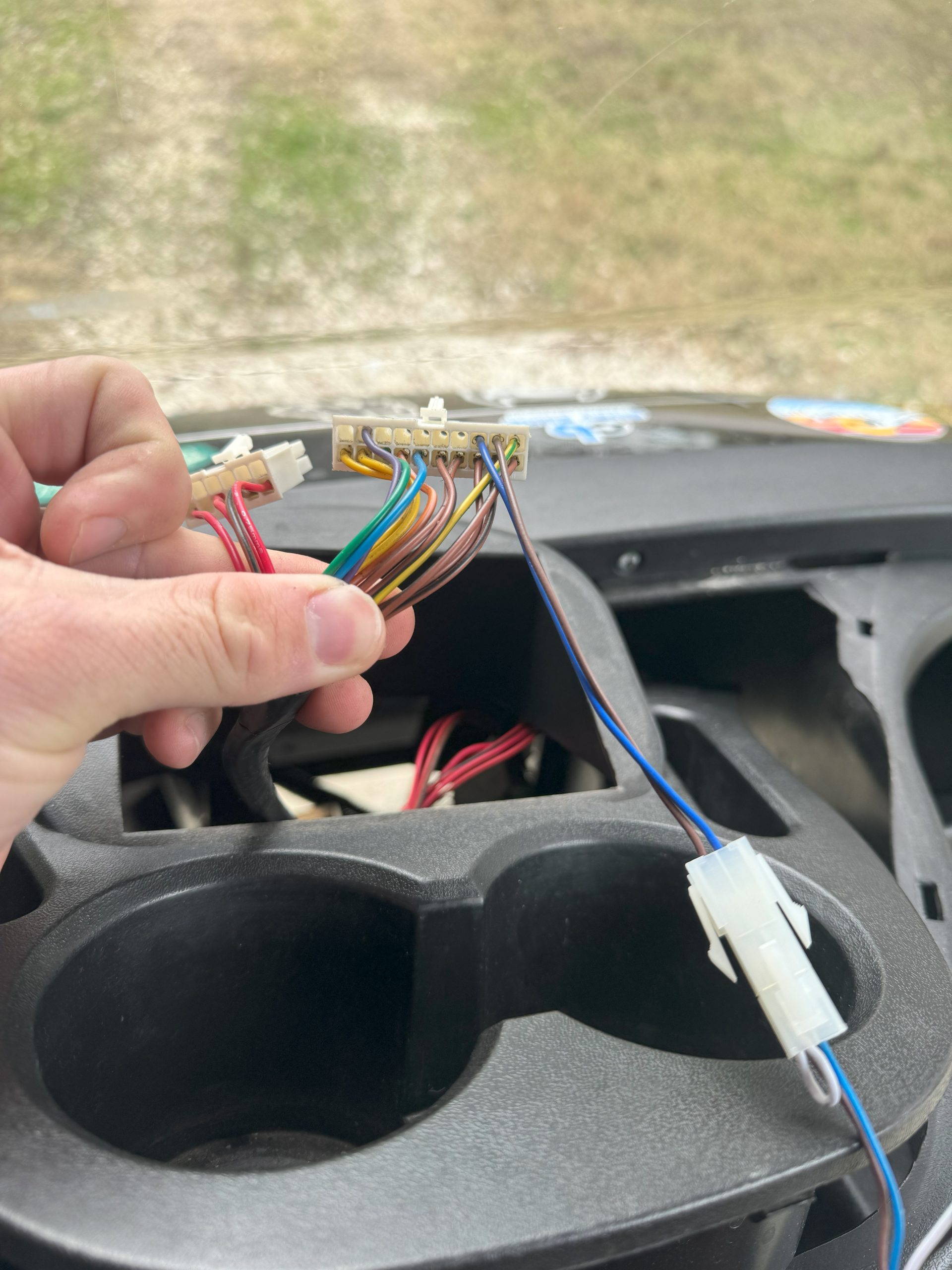
CAN dongle that connects to 4-pin harness of battery cable.
Blue and brown wires installed into 20-pin wiring harness
One thing to be aware of is that your odometer reading is stored in the cluster itself – so replacing it will reset your odometer and hours to 0.
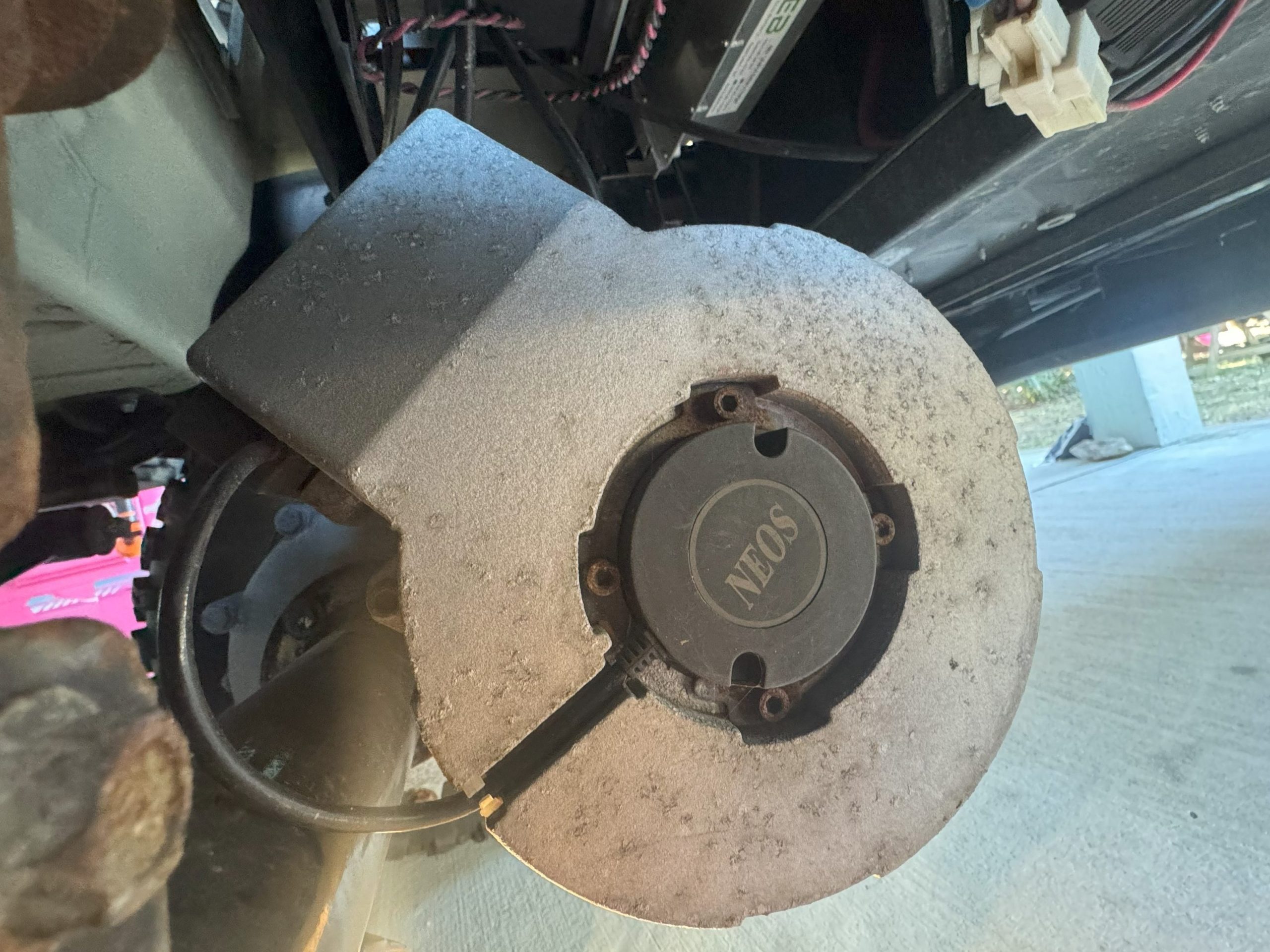
The speedometer on my Advanced EV1 6L has always been off by 1-2mph. I recently replaced my instrument cluster and found it was off nearly 6mph. In researching this issue, it appears the EV1 with Neos controllers use an external Hall effect speed sensor attached directly to the motor, sending the signal directly to the instrument cluster. The cluster has firmware flashed specifically to the gear ratio and tire size that calculates the cart speed. None of the settings in the Neos controller affect this calculation and there is currently not a documented way to re-flash the firmware on the Hefei Huanxin Technology Development Company controller.
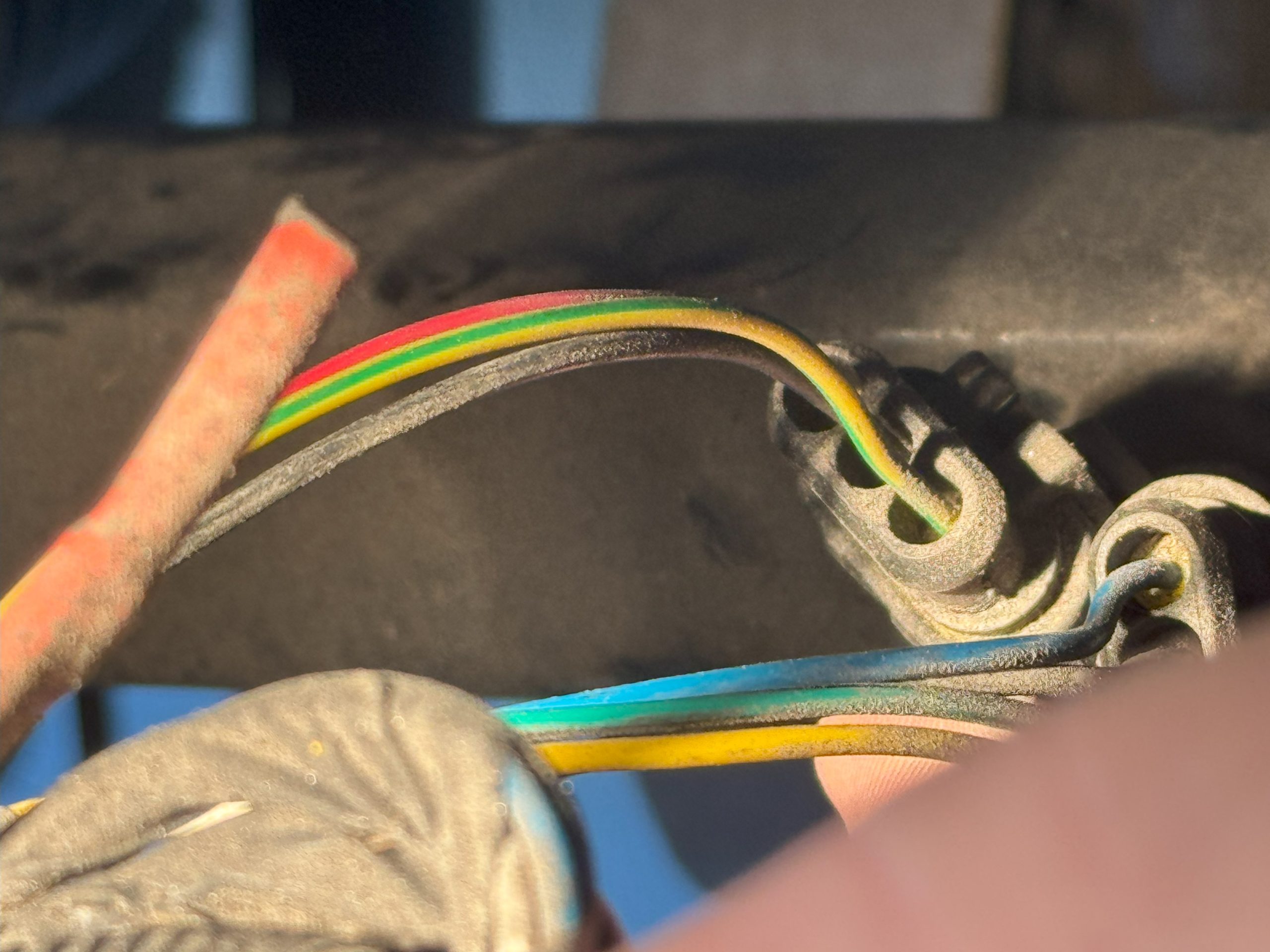
Hall effect speed sensors typically output a square wave at 5V or 12V DC. Reviewing the wiring diagram for the A627 I was able to see the green/yellow wire mapped to pin 1 of the instrument cluster carries the signal from the speed sensor attached to the AC motor.
After removing the controller cover located under the rear seat, you’ll find two wiring harnesses that connect to the motor – one for the encoder and one for the speed sensor.
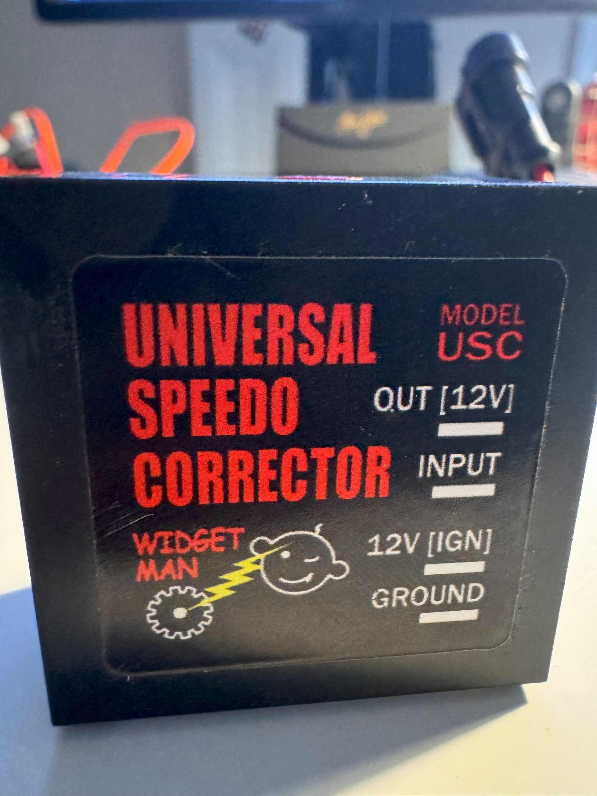
The speed sensor delivers 4 pulses per revolution according to the label on the cluster. I decided to connect an oscilloscope (used the EspoTek Labrador attached to my Surface Go for this) and confirmed it output a 12V square wave. In order to change the output of the sensor, I investigated using a frequency divider to adjust the signal. There are several reference specifications for building this type of circuit, but I found a purpose-built device from Widget Man that suits the need at a reasonable cost – the Univeral Speedometer Corrector.
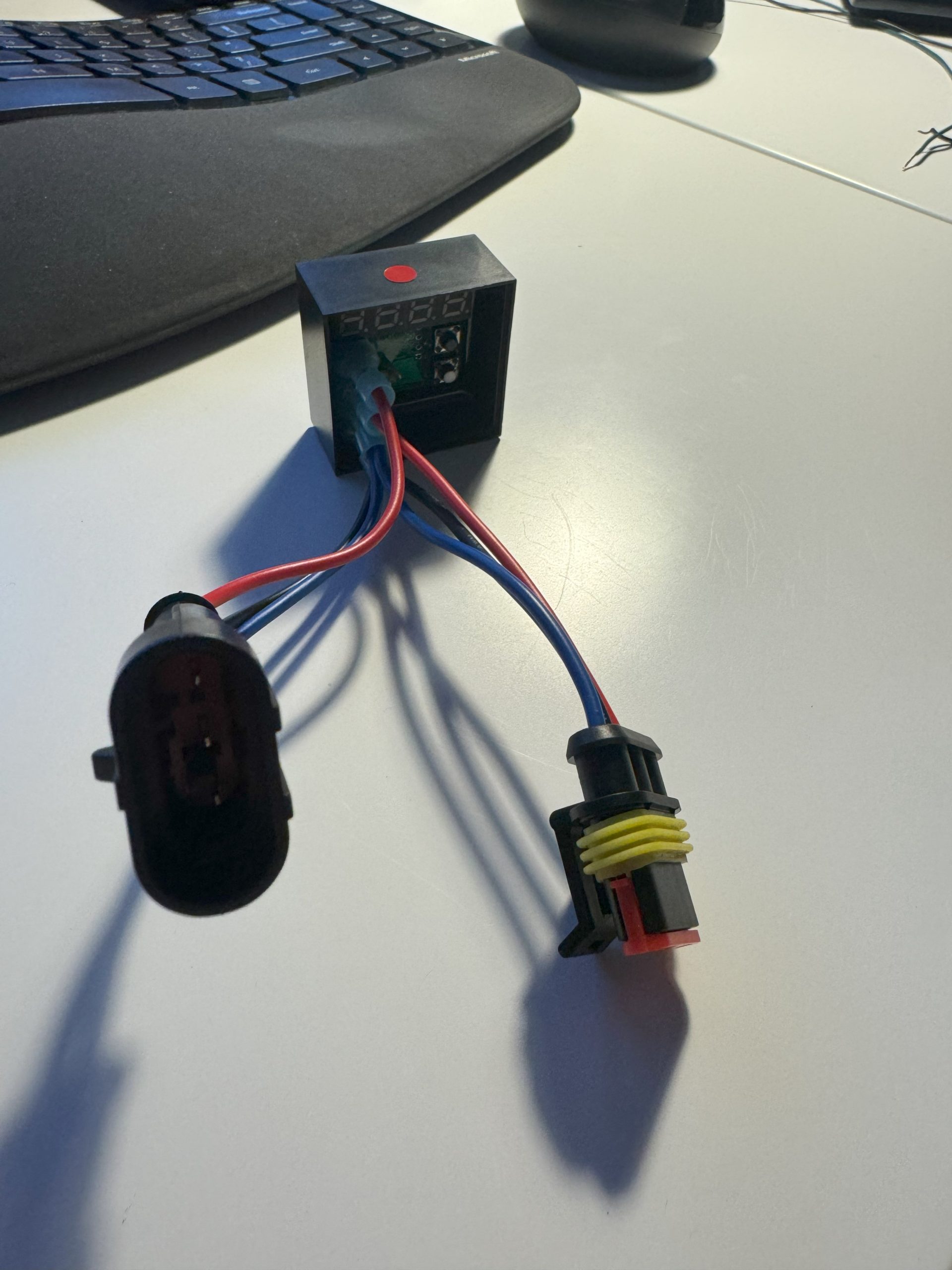
To simplify installation in the cart, I used the 3-pin automotive DJ7031 connectors and 0.25″ FASTONS – you can find both of these at your local automotive store or on Amazon. This enables the device to use the existing 12V DC feed for the sensor for power and ensure a water-tight connection.
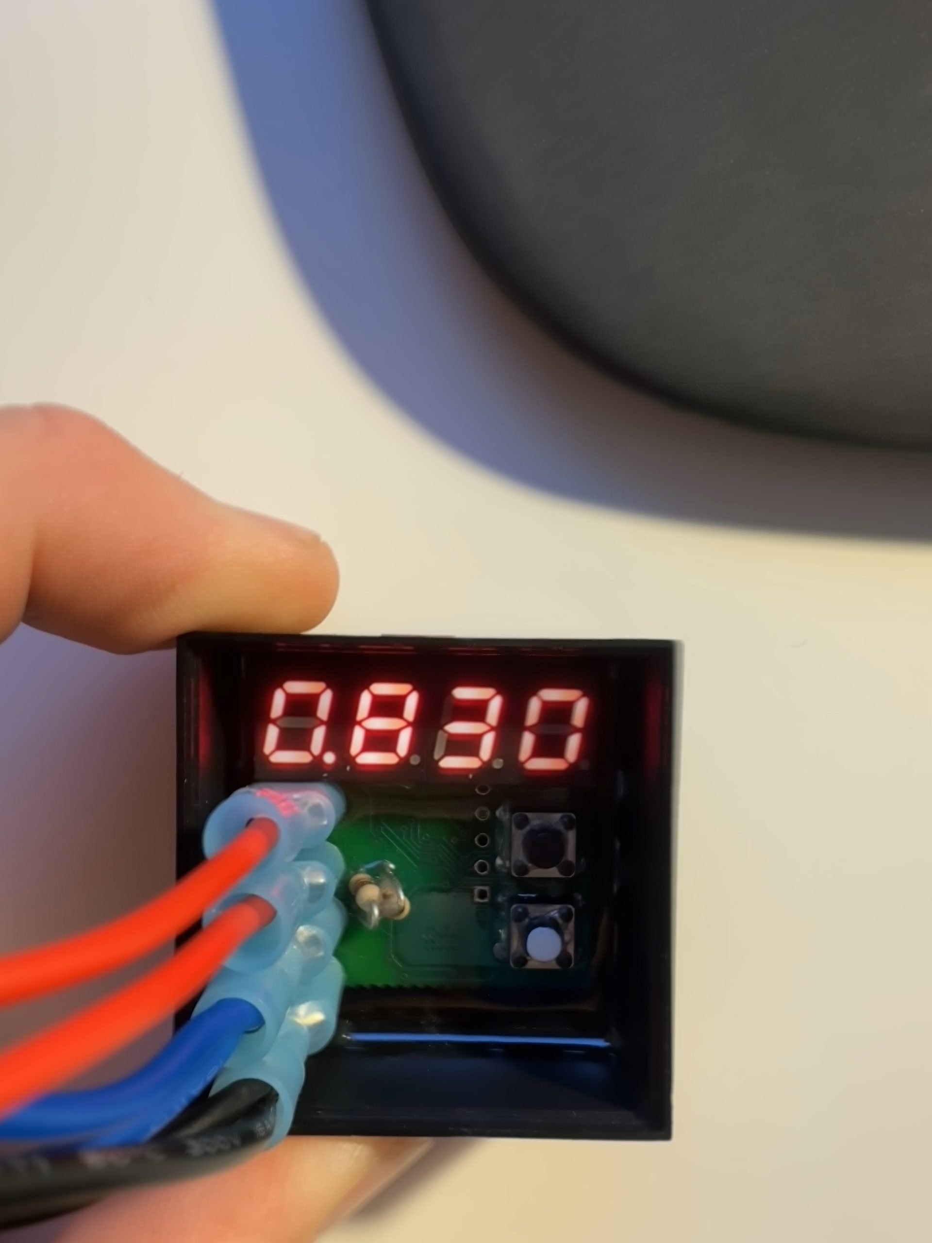
The Speedo Corrector has a digital output and two buttons that enable you to adjust input signal from 1.5% to 6000%. There are also pull-up resistors to deal with various types of installations – we leave both resistors in-tact for our use case. Since my cart was displaying 34mph and GPS had it at 28mph, I set it to 0.830 (28/34 = 0.8235).
Last step was using a few zip times to hold it in place and connect it to the existing wiring harness for the speed sensor.