Odometer adjustment for LV Tong LSV clusters

The odometer reading for LV Tong LSV’s is stored on the firmware of the instrument cluster. There is currently not a documented way to flash the firmware of the Hefei Huanxin Technology Development Company cluster. However, the odometer is calculated based on the speed sensor signal which can be emulated. By using a signal generator at a high frequency, you can increase the odometer reading of the cluster.

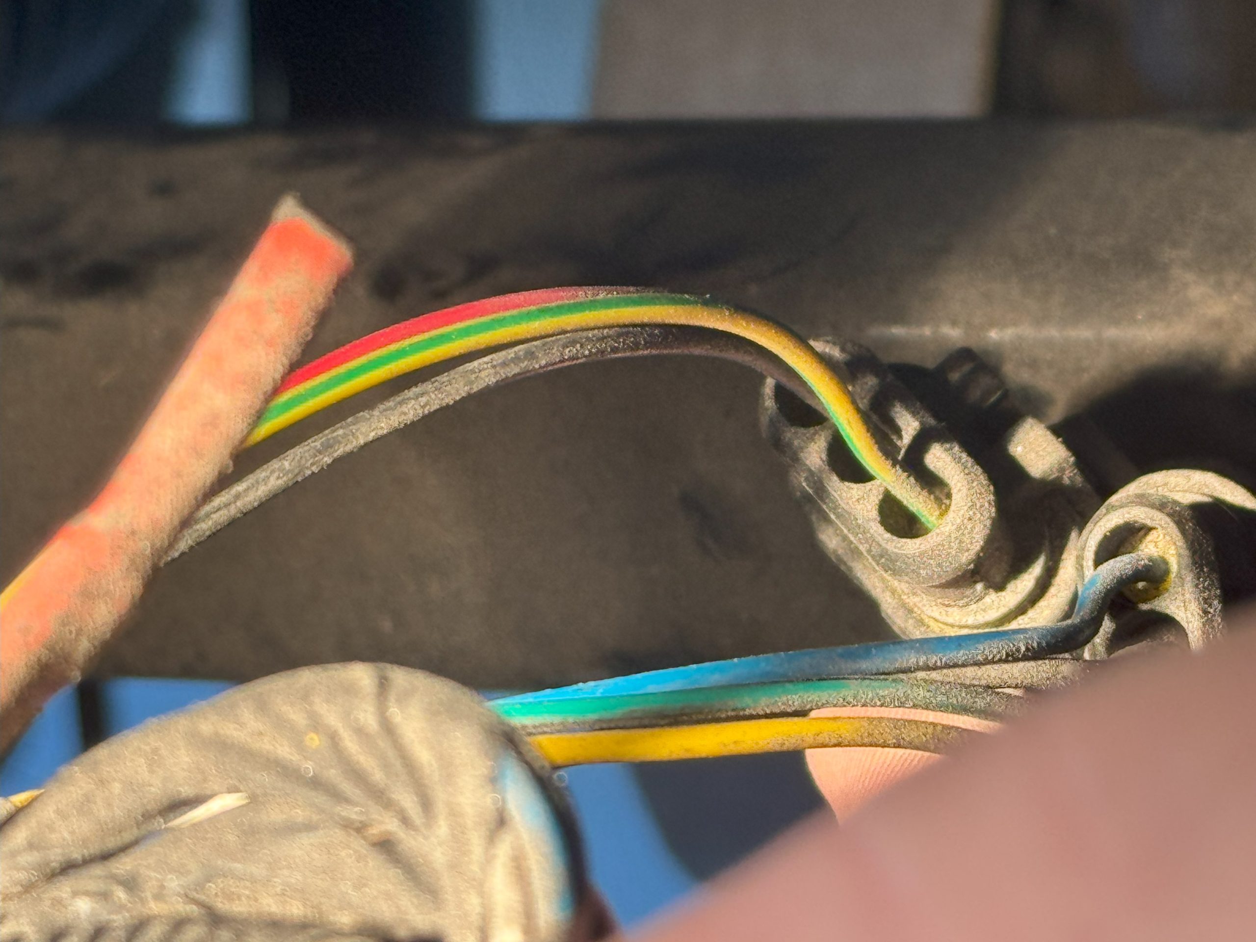
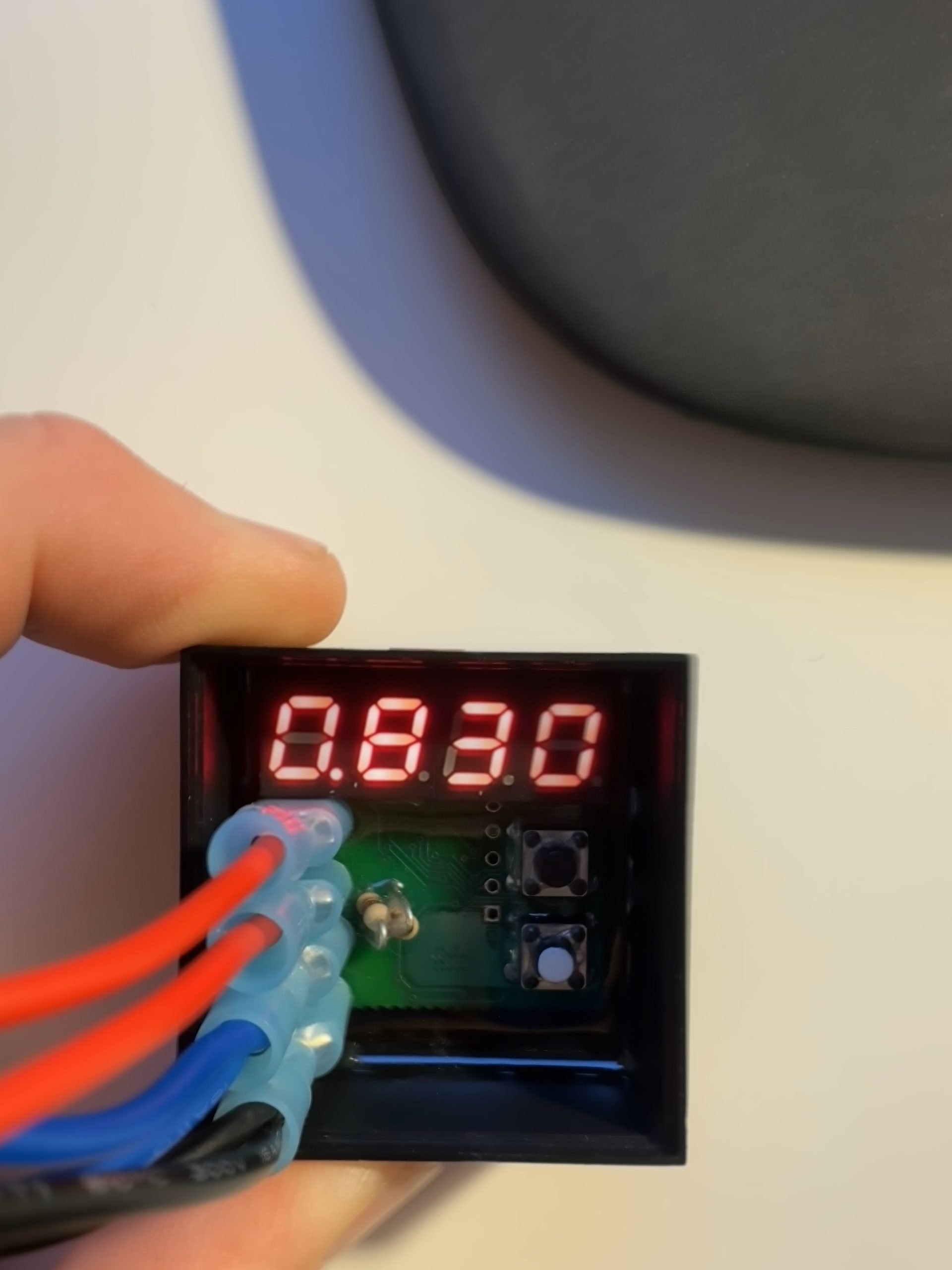
The speed signal is carried on the yellow/green wire connected to pin 1 of J1 on the cluster. Connect the output of a signal generator to this pin (I used the EspoTek Labrador attached to my Surface Go for this) using at least a 3V square wave (the speed sensor on the LSV outputs 12V, but the cluster seems to detect anything over 3V). Be sure your signal generator’s ground is connected to same ground as the power supply otherwise the cluster may not properly detect the signal. The maximum frequency will depend on your specific firmware but the cluster doesn’t seem to be able to process speeds above ~860mph – setting a frequency that generates a speed higher than this doesn’t seem to matter. For mine (580mm tire diameter, 14:1 gear ratio, 4 pulses per rotation) the maximum frequency it could sustain was 13.5kHz (~1000mph).

Adding miles to my replacement cluster to match the original odometer reading

Speedometer adjustment for LV Tong based LSV’s with Neos controllers

The speedometer on my Advanced EV1 6L has always been off by 1-2mph. I recently replaced my instrument cluster and found it was off nearly 6mph. In researching this issue, it appears the EV1 with Neos controllers use an external Hall effect speed sensor attached directly to the motor, sending the signal directly to the instrument cluster. The cluster has firmware flashed specifically to the gear ratio and tire size that calculates the cart speed. None of the settings in the Neos controller affect this calculation and there is currently not a documented way to re-flash the firmware on the Hefei Huanxin Technology Development Company controller.

Hall effect speed sensors typically output a square wave at 5V or 12V DC. Reviewing the wiring diagram for the A627 I was able to see the green/yellow wire mapped to pin 1 of the instrument cluster carries the signal from the speed sensor attached to the AC motor.

After removing the controller cover located under the rear seat, you’ll find two wiring harnesses that connect to the motor – one for the encoder and one for the speed sensor.

The speed sensor delivers 4 pulses per revolution according to the label on the cluster. I decided to connect an oscilloscope (used the EspoTek Labrador attached to my Surface Go for this) and confirmed it output a 12V square wave. In order to change the output of the sensor, I investigated using a frequency divider to adjust the signal. There are several reference specifications for building this type of circuit, but I found a purpose-built device from Widget Man that suits the need at a reasonable cost – the Univeral Speedometer Corrector.

To simplify installation in the cart, I used the 3-pin automotive DJ7031 connectors and 0.25″ FASTONS – you can find both of these at your local automotive store or on Amazon. This enables the device to use the existing 12V DC feed for the sensor for power and ensure a water-tight connection.

The Speedo Corrector has a digital output and two buttons that enable you to adjust input signal from 1.5% to 6000%. There are also pull-up resistors to deal with various types of installations – we leave both resistors in-tact for our use case. Since my cart was displaying 34mph and GPS had it at 28mph, I set it to 0.830 (28/34 = 0.8235).

Last step was using a few zip times to hold it in place and connect it to the existing wiring harness for the speed sensor.