Adding additional VIP to Azure Load Balancer

Recently, a partner needed guidance on adding an additional VIP to an Azure Load Balancer. This is a typical scenario where multiple SSL-based websites are running on a pair of servers and clients may not have SNI support, necessitating dedicated public IP’s for each website. Azure Load Balancer in Azure Resource Manager does support multiple VIP’s, just not via the portal. Not to worry, Powershell to the rescue. The Azure documentation site has a great article describing the process of deploying a two-node web farm and internet facing load balancer. These commands assume you’ve already deployed the load balancer and are just adding a second VIP:

Login-AzureRmAccount
Select-AzureRmSubscription -SubscriptionId 00000000-0000-0000-0000-000000000000
 
#Get the Resource Group
$rg = Get-AzureRmResourceGroup -Name "MultiVIPLBRG"
 
#Get the Load Balancer
$slb = Get-AzureRmLoadBalancer -Name "MultiVIPLB" -ResourceGroupName $rg.ResourceGroupName
 
#Create new public VIP
$vip2 = New-AzureRmPublicIpAddress -Name "PublicVIP2" -ResourceGroupName $rg.ResourceGroupName -Location $rg.Location -AllocationMethod Dynamic
 
#Create new Frontend IP Configuration using new VIP
$feipconfig2 = New-AzureRmLoadBalancerFrontendIpConfig -Name "MultiVIPLB-FE2" -PublicIpAddress $vip2
$slb | Add-AzureRmLoadBalancerFrontendIpConfig -Name "MultiVIPLB-FE2" -PublicIpAddress $vip2
 
#Get Backend Pool
$bepool = $slb | Get-AzureRmLoadBalancerBackendAddressPoolConfig
 
#Create new Probe
$probe2 = New-AzureRmLoadBalancerProbeConfig -Name "Probe2" -RequestPath "/" -Protocol http -Port 81 -IntervalInSeconds 5 -ProbeCount 2
$slb | Add-AzureRmLoadBalancerProbeConfig -Name "Probe2" -RequestPath "/" -Protocol http -Port 81 -IntervalInSeconds 5 -ProbeCount 2
 
#Create Load Balancing Rule
$slb | Add-AzureRmLoadBalancerRuleConfig -Name Rule2 -FrontendIpConfiguration $feipconfig2 -BackendAddressPool $bepool -Probe $probe2 -Protocol TCP -FrontendPort 80 -BackendPort 81
 
#Save the configuration
$slb | Set-AzureRmLoadBalancer

Linking spam sent through shared IIS SMTP server to a user

As a web host, one of the most time-consuming processes is investigating spam sent through mail servers. Many legit websites have forms and other functions that send email to users. If left unchecked, spammers can leverage these to send unsolicited mail.

In our environment, we enable the IIS SMTP role on our web servers and configure them to allow relaying only from localhost with basic authentication. This means that only local sites hosted in IIS can send mail and they have to provide a username and password to do so. Unfortunately, the IIS SMTP service does not log that username – it’s long been a point of contention with the IIS SMTP service. Most administrator’s recommendations suggest using another service, such as SmarterMail. However, there are ways to extract the authenticated username sending spam.

In order to use this method, you’ll need to capture a packet trace while spam is being sent. This will allow you to see the entire SMTP transaction between client and server. The catch here is that we are using localhost and most packet capture utilities cannot capture loopback traffic. Wireshark has an article that goes into detail about why it can’t capture loopback traffic. There is a utility that we can use called RawCap that will capture this local traffic at the socket level and output it into a format that Wireshark can parse. So, depending on the source of the spam, you’ll either want to use Wireshark (for remote) or RawCap (for local) to capture network data.

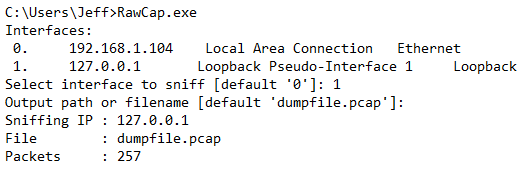
RawCap has an interactive prompt to guide you through the capture process:

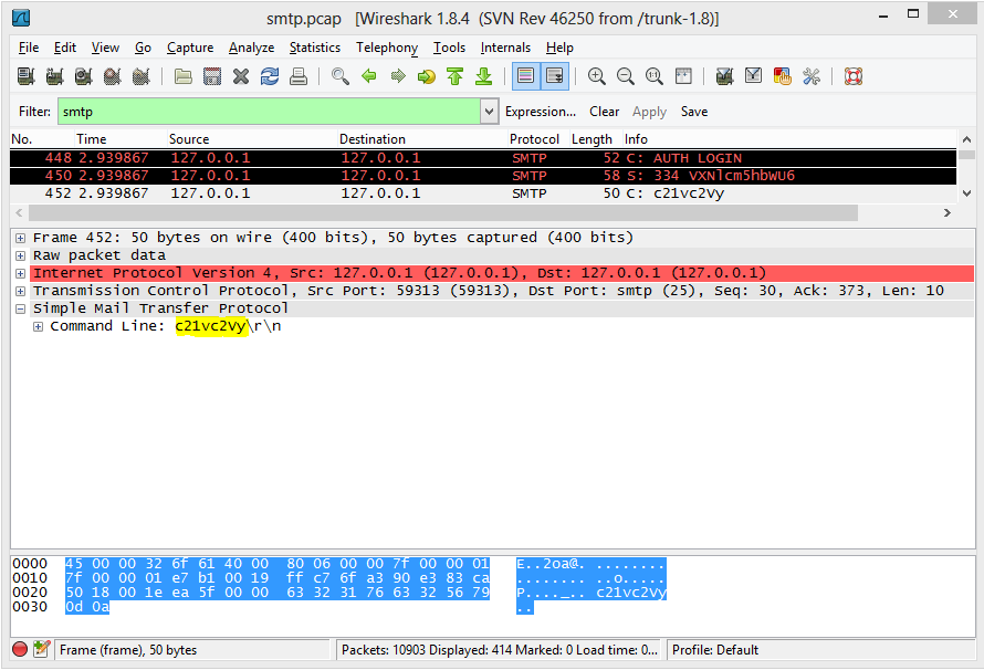
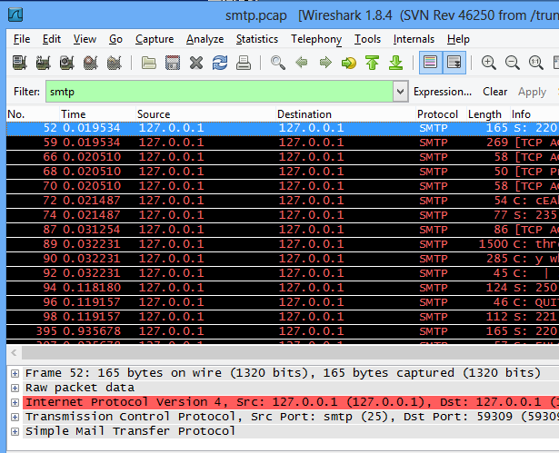
Once you’ve capture sufficient traffic, you can cancel the capture by hitting Ctrl+C and then opening the resulting file in Wireshark for analysis. You’ll likely have a lot of network “noise” that you’ll want to filter out by using a filter of “smtp”:

From here, we can drill down to the AUTH LOGIN command sent by the client, and a 334 response from the server:

To explain what’s happening here, after the EHLO command, the server responds with what verbs it supports. The client then issues the AUTH LOGIN command and the server responds with “334 VXNlcm5hbWU6" where "VXNlcm5hbWU6" is a BASE64 encoded string "Username:". The client then responds with the BASE64 encoded username. We can decode this value on base64decode.org to find the username sending spam.

Windows Azure VPN Walkthrough

A recent project has us testing out some of the new Windows Azure features. One important configuration step is getting the Windows Azure environment connected to our on-premise network. To do this, we create a site to site VPN tunnel between an Azure virtual network and your existing on-premise corporate environment. Typically, this is done using VPN hardware (such as Cisco, Fortinet, or Juniper) but can also be done using Windows Server. Microsoft has a decent tutorial on how to create an Azure virtual network with cross-premises connectivity, but it lacks some information about the configuration of the remote end.

First, let’s get a virtual network created in Azure.

1. Login to the Azure Preview Portal.

2. In the left-hand column, select Networks, and then click Create on the bottom banner.
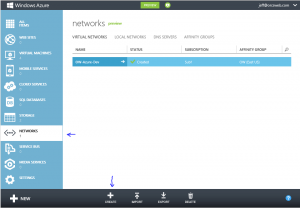
3. This will bring up a wizard for creating a virtual network. Give the network a name and either select an existing affinity group if you have one, or create a new one. Virtual Networks must belong to an affinity group and can only be used with VM’s in the same affinity group. Click Next

4. The next screen asks you to define address space and logical subnets. You can use super-netting here to define a large address space (eg. 10.1.0.0/16) and then create logical subnets to group servers (eg. 10.1.1.0/24) for specific server purposes. Define the address space and at least 1 subnet. Click next.

5. On the DNS Servers and Local Network screen, you’ll want to configure a DNS server for this virtual network. For DNS, this will be the DNS server your VM’s in this virtual network use. The Local Network settings require both a Gateway subnet and a Local network. The Gateway network should be a logical subnet of the address space you previously defined (ie. 10.1.0.0/24) and is used only for to run necessary gateway services. The Local network should be networks configured in your on-premise environment. Select Create New Local Network and click next.

6. On the Create New Local Network Screen you’ll need to assign a name to the Local Network, define the VPN endpoint in your on-premise environment and one or more subnets in the Address Space (eg. 10.4.0.0/16) corresponding to local networks configured in your on-premise environment. Click the check mark to create the virtual network.

Now that a virtual network has been created, we need to create a VPN gateway for the network.

1. From the Azure portal, select Networks and then click the name of the virtual network you just created.
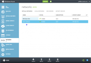
2. You should see an indicator that a Gateway has not yet been created. Click the Create Gateway icon in the bottom banner. Click the Yes check mark that appears in the bottom banner to start the Create Gateway job.
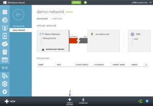
3. It may take up to 15 minutes for the Gateway to be created. A message should appear that the Gateway creation has started.
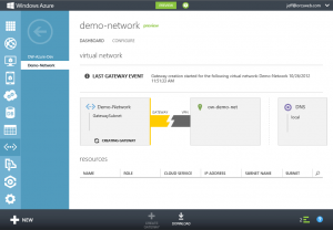
4. Once completed, a Gateway IP Address will be displayed along with incoming and outgoing data metrics. You’ll need the pre-shared key information to configure the tunnel on your end. Click the View Key button in the bottom banner.

Lastly, you’ll need to configure the site to site VPN tunnel on your VPN hardware device on your on-premise equipment. The following is an example of the necessary information:

Phase 1 (IKE)
Remote Endpoint/Peer IP: Virtual Network Gateway address (this is the Gateway IP Address listed for the virtual network in the Azure portal)
Authentication Method: Pre-shared key
Pre-shared Key: <value from View Key in Azure portal>
Phase 1 Proposal: Encryption AES-128 (or AES-128-CBC), Authentication SHA1
Phase 1 Keylife: 28800s
Phase 1 DH Group: 2

Phase 2 (IPsec)**
Local Network: Local corporate subnet (this is the Local Network you configured when setting up the Azure virtual network)
Remote Network: Azure Virtual network (this is the Address Space you configured when setting up the Azure virtual network)
Phase 2 Proposal: Encryption AES-128 (or AES-128-CBC), Authentication SHA1 (or SHA1-HMAC-96)
Phase 2 Keylife: 3600s AND 102400000 KBytes
Phase 2 DH Group (PFS): Disabled

**Note: Normally, you use the defined subnets in Phase 2. However, I’ve found in practice that the Azure gateway uses 0.0.0.0/0 for Phase2:

2013-05-01 11:33:21 ike 1:OW-Azure:13537:6612914: peer: type=7/7, local=0:0.0.0.0-255.255.255.255:0, remote=0:0.0.0.0-255.255.255.255:0
2013-05-01 11:33:21 ike 1:OW-Azure:13537:6612914: mine: type=7/7, local=0:10.4.0.0-10.4.255.255:0, remote=0:10.1.0.0-10.1.255.255:0
2013-05-01 11:33:21 ike 1:OW-Azure:13537:6612914: no matching phase2 found
2013-05-01 11:33:21 ike 1:OW-Azure:13537::6612914: failed to get responder proposal
2013-05-01 11:33:21 ike 1:OW-Azure:13537: failed to create child SA
2013-05-01 11:33:21 ike 1:OW-Azure:13537: sending error response

If the subnets do not match on both ends, the tunnel will not establish, so you’ll want to use 0.0.0.0/0 for your Phase 2 subnets in the VPN configuration.

You can download a sample configuration script for Cisco ASA, ASR, and ISR or Juniper SRX, J, ISG or SSG systems from the Azure portal by clicking the Download link in the bottom banner (next to the View Key button). You’ll need to modify the script with the proper networks and key. That being said, the scripts assume some things about your configuration so it’s best to configure your end of the VPN tunnel manually. For instance, the script may try to may try to adjust the maximum segment size to 1350 on your VPN device’s external interface which could impact your other configured tunnels. It’s also important to note that firewall and NAT rules are typically required on most VPN hardware devices.

To test connectivity, simply initiate traffic from either side of the tunnel (ie. ping 10.1.1.10 from 10.4.1.10). It helps to have debug trace messages enabled on your VPN hardware device in case of issues. Happy tunneling!
Cisco VPN Client on Windows 8

Just upgraded my late 2007 MacBook Pro Boot Camp partition to Win 8 RTM and was in the process of re-installing several apps. The Cisco VPN Client we use to connect to our corporate network was a bit finicky. There are a few workarounds to get it running on Win8.

First, you need to fix the following registry key to resolve error 442 Unable to enable virtual adapter:

HKEY_LOCAL_MACHINE\SYSTEM\CurrentControlSet\Services\CVirtA\DisplayName

It will be set to something like “@oem8.inf,%CVirtA_Desc%;Cisco Systems VPN Adapter for 64-bit Windows” – drop everything before “Cisco Systems” from that value.

Next, when using certs, you cannot use your certificate from the local user store. Rather, import the certificate to the local computer store and delete it from your user store. This should resolve error 403 Unable to contact the security gateway.

Multithreaded Powershell Port Scanner

We recently had to perform a hardware upgrade of a perimeter firewall. Doing so is a major undertaking, and while we have very good documentation, it’s always important to do some real-world testing.

To facilitate this, we needed to perform some port scanning from outside our network to ensure that A) All of our firewall rule documentation matched what was actually configured, and B) Ensure a smooth transition to the new hardware. Most port scanners I found were capable of scanning a port range for a given IP set. But I wasn’t able to find much of anything that could take specific IP/port data and return the results. I had previously written a simple ASP.NET application to do this, but it wasn’t designed for testing large datasets.

ASP.NET Port Scanner

So, I decided Powershell was the best bet. There were several available examples, but nothing that truly did what we needed. I was able to pull several resources together and came up with the attached Powershell script. Credit for the port detection goes to Boe Prox, to Gaurhoth for the IP range powershell functions, and to Oisin Grehan for the multithreading code.

The result is a script that takes a CSV input and outputs the results to CSV. You can specify IP addresses (eg. 192.168.100.1), CIDR subnets (192.168.1.0/24, 10.254.254.16/28, and/or IP ranges (10.0.1.1-10). The services.xml file in the bin folder contains a powershell object with port settings for various well-know ports and can be modified to meet your needs. Port cans be specified using their well-known name (eg. SMTP, RDP, HTTP) or in a protocol/portNum format (eg. tcp/80, udp/53, tcp/4900-4910).

Scanning is fairly quick:

PS D:\temp\portscanner> .\PortScanner.ps1 Importing Data from .\externalrules.csv
Imported 3033 targets
Flattening targets into endpoints
There are 3996 to scan
Begin Scanning at 07/08/2011 15:58:31
Waiting for scanning threads to finish...
We scanned 3996 endpoints in 399.1811698
Exporting data to .\results.csv

Happy networking!

portscanner

Network Uptime

We upgraded the firmware on some network devices at OrcsWeb during last month’s maintenance window. Before that, they had some impressive uptime:

Firewall Uptime

Switch Uptime

The devices are configured with HA redundancy, so the rolling firmware upgrades went beautifully with minimal downtime during the route convergence and no manual intervention.

High CPU on Cisco 4500 with MSFT NLB multicast cluster

Recently, we were alerted to higher than normal CPU on some of our core Cisco Catalyst 4507 switches running IOS 12.2. Using Cisco’s CPU troubleshooting doc, I was able to narrow down the source to the Cat4K Mgmt LoPri process. From there, issuing a “sh platform health” command found it was the K2CpuMan Review process meaning packets are being forward by the CPU. To find out which queue, we issued the “sh platform cpu packet statistics” command. That showed the L3 Fwd Queue was much higher than normal.

By creating a CPU span and monitoring the traffic with Network Monitor 3.3, we could see that all of the traffic destined for VIP’s in our 2008 NLB clusters was hitting the CPU. I checked the configuration to ensure it matched the Catalyst and MSFT NLB example on Cisco’s site which it did. We were using multicast NLB configuration as explained in the document. I setup a test NLB cluster to play with the settings to figure out why cluster bound packets were hitting the CPU. What I found was in relation to this section:

However, since the incoming packets have a unicast destination IP address and multicast destination MAC the Cisco device ignores this entry and process-switches each cluster-bound packets. In order to avoid this process switching, insert a static mac-address-table entry as given below in order to switch cluster-bound packets in hardware.

mac-address-table static 0300.5e11.1111 vlan 200 interface fa2/3 fa2/4

Note: For Cisco Catalyst 6000/6500 series switches, you must add the disable-snopping parameter. For example:

mac-address-table static 0300.5e11.1111 vlan 200 interface fa2/3 fa2/4 disable-snooping

The disable-snooping parameter is essential and applicable only for Cisco Catalyst 6000/6500 series switches. Without this statement, the behavior is not affected.

I double and triple checked that our switches had the satic mac entry for the CAM tables and they did. So, I reconfigured my test cluster from the ground up and found that cluster bound packets only hit the cpu AFTER this command was entered. By removing this command from my switches for our production, CPU dropped 30-40% instantly. This seems to contradict what Cisco has posted in their example.

There was no adverse affect or downtime from removing this command. Both cluster nodes are connected locally to the switch however, and this command may be necessary if a NLB node is connected to a down-level swtich. Furthermore, a “sh int stats” is showing that no packets are switched by the “processor.”

Using RPC custom port range with Windows Firewall

I ran into an interesting issue today. We use a dedicated port range for RPC connections through firewall per this Microsoft article. Doing so allows RPC to work through dedicated hardware firewalls. We also enable the local Windows firewall on several boxes as this provides a firewall for any systems not using a dedicated piece of hardware or from other systems behind dedicated firewalls.

While using Shavlik NetChk Configure to scan systems for compliance, I noticed some inconsistencies which I traced back to a firewall issue on the server being scanned. The scans perform some of the checks over RPC. I confirmed that Remote Administration had been enabled using this command:

netsh firewall set service REMOTEADMIN enable

However,  netstat would show the connection in a SYN_SENT state on a port in the dedicated RPC range. Buried in this technet article, I found the reason:

Remote Administration Adds TCP ports 135 and 445 to the exceptions list. Also adds Svchost.exe and Lsass.exe to the exceptions list to allow hosted services to open additional, dynamically-assigned ports, typically in the range of 1024 to 1034. This setting allows a computer to be remotely managed with administrative tools, such as the Microsoft Management Console (MMC) and Windows Management Instrumentation (WMI). It also allows a computer to receive unsolicited incoming Distributed Component Object Model (DCOM) and remote procedure call (RPC) traffic.

It seems that when setting a custom range of ports for RPC via the HKLM\Software\Microsoft\RPC\Internet key, it “breaks” the Remote Administration firewall rule in the Windows Firewall. This was tested on a Server 2003 R2 SP2 system, but I suspect similar issues would apply to Server 2008.

Windows 2003 SP2 Network Issues

Included with SP2 is the Scalable Networking Pack which was a redeisgn of some major networking components to offload some of the processing to onboard components of certain network cards. Unfortunately, this seems to still be in its infancy and we started noticing very strange problems right away. A colleauge found this post on the MS Exchange team’s blog which ultimately led us to the answer: http://msexchangeteam.com/archive/2007/07/18/446400.aspx.

The symptoms we noted on our side were specifically that OS X users behind certain NAT firewalls would timeout when trying to retrieve pages from our web servers. After weeks of troublehsooting, we finally narrowed it down to a problem where pages less than 1440 bytes worked fine, but larger pages simply timed out. We also noticed that some of our technicians had problems connecting via RDP to various servers. The initial connection would drop, but sub-sequent connections worked find. Most of our Dell systems have onboard Broadcom NIC’s. Supposedly, this new Networking Pack which is enabled by default works only with the latest drivers. However, we found that even using the latest drivers provided directly from Broadcom, we were still having problems.

Luckily, the fix does not require a reboot and is easily implemented. Simply disabling the tcp chimney offload solved all of our issues:

netsh int ip set chimney disabled

You can view the state of each of the connections to the server and their offload state by running the netstat -t command.

Port Trunking in Cisco IOS

Port trunking is the process by which ports are designated as common uplink ports to carry traffic from multiple VLANs across the same physical cable. In the following example, we enable trunking on an etherchannel group to carry specific traffic from VLANs 1 through 99. We also assign the channel to a vlan we’ve designated specifically for etherchannels.

Router# configure terminal
Router (config)# interface port-channel 1
Router (config-if)# switchport access vlan 100
Router (config-if)# switchport trunk encapsulation dot1q
Router (config-if)# switchport trunk allowed vlan 1-99
Router (config-if)# switchport mode trunk
Router (config-if)# ^Z

This configuration will carry traffic for vlans 1-99 across channel group 1. Setting the trunk encapsualtion type is only available on switches that support multiple encapsualtion types. Ensure that spanning-tree is on in order to prevent loops.