With the RTM release of the Service Management Portal from Microsoft, hosters can configure VMM 2012 SP1 to allow self-service tenants to create NVGRE networks for use with VM’s deployed through the portal. The VMM Engineering Blog has a great post that provides a basis for understanding how Network Virtualization is configured in VMM 2012 SP1.
The process can be summarized as follows:
- Create a Logical Network with a Network Site & Subnet for use as the Provider Address.
- Create an IP Pool on the Logical Network for the Provider Address space.
- Create a Host Port Profile linked to the Network Site created in step 1.
- Optional: Create a port classification and profile for the virtual adapter. This will allow you to enable DHCP and Router guard on your templates and hardware profiles.
- Create the Logical Switch referencing the Host Port Profile (and Virtual Port Classification and Profile if you created them).
- Assign the Logical Switch to your Hyper-V hosts.
- Assign the Logical Network to your Cloud.
- Create a default VM Network for use with templates and hardware profiles.
To create the logical network, in VMM, go to Fabric > Networking > Logical Network and select Create Logical Network from the ribbon menu. Give the network a name (this is what will appear in the Katal portal) and select the “Allow new VM networks created on this logical network to use network virtualization” checkbox, then click Next.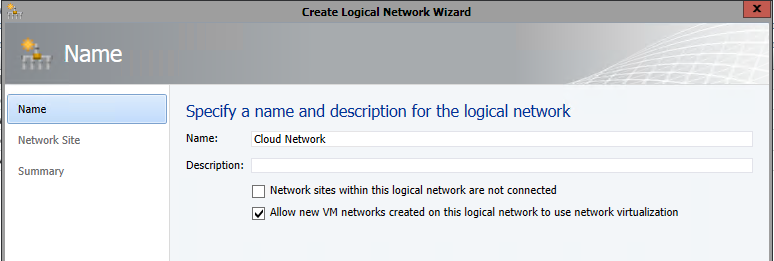
Add a new network site to be used as the Provider Address network. This is what the Hyper-V hosts will use to communicate with one another.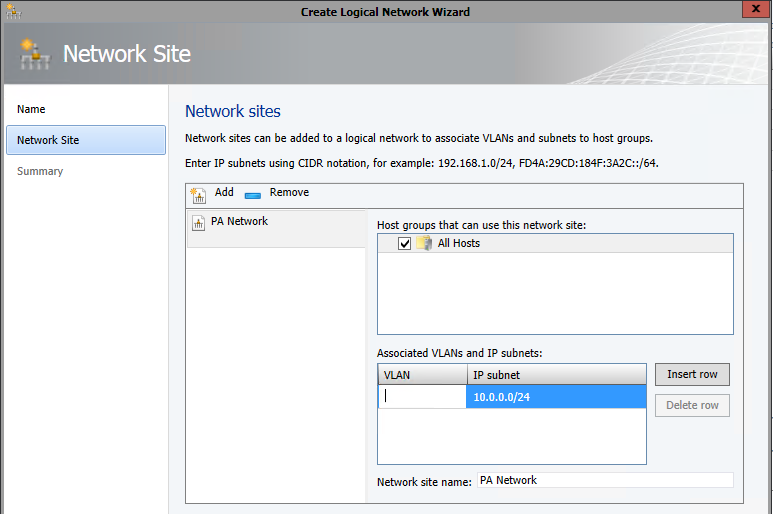
Now that a Logical Network and Site have been created, we’ll need to create an IP Pool for the Provider Addresses. Right-click on your logical network, and select Create IP Pool. 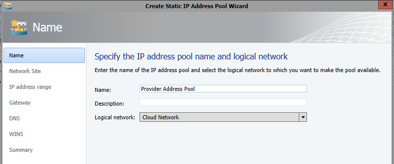
Associate the Pool with the Network Site we created in the previous step.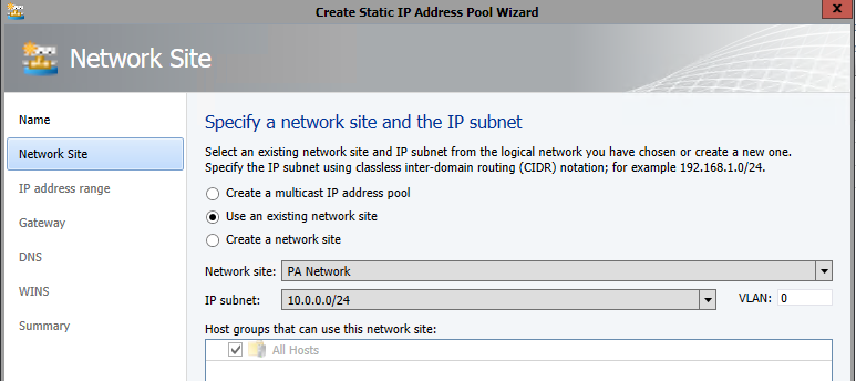
You can leave the default range and specify gateway and DNS settings if your Hyper-V hosts span multiple subnets. Next, we’ll want to create a Host Port Profile and associate it with the network site. Right-click Fabric > Networking > Native Port Profiles and select Create Native Port Profile. Name it appropriately and change the type to Uplink port profile.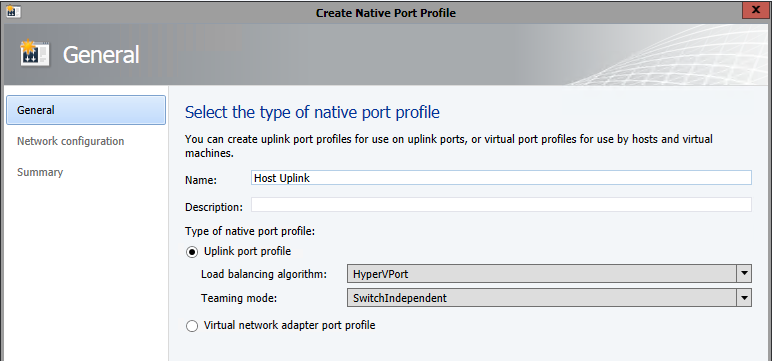
Associate the Port Profile with the Network Site we created on the Logical Switch and check the checkbox to Enable Windows Network Virtualization. Click Next and Finish.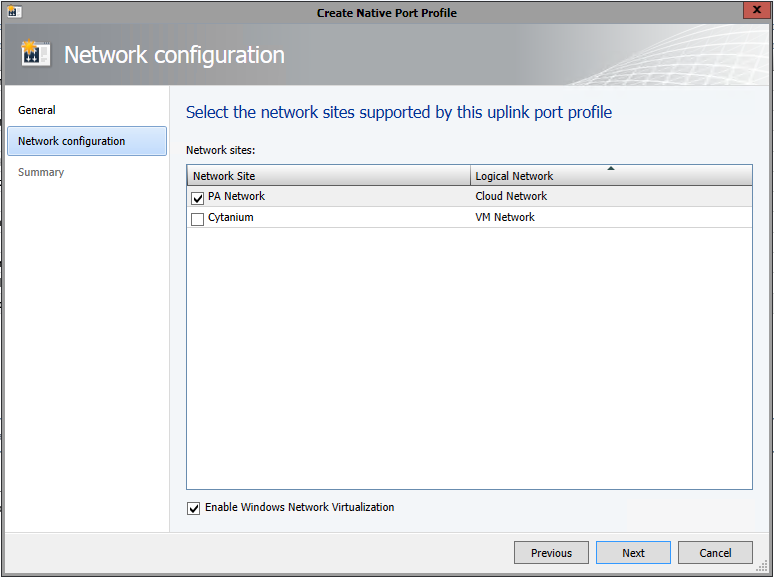
Optionally, you can create a virtual port classification and profile. This will allow you to enable/disable virtual adapter features or create tiers of service. Next, we can create the Logical Switch. From Fabric > Networking > Logical Switches select Create Logical Switch in the ribbon. Give the Switch a name and specify extensions as necessary. Associate the Uplink port profile we created in the previous step.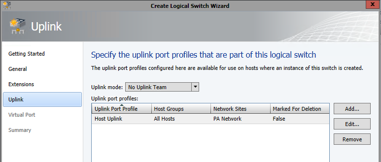
Add you virtual port profiles if you created them and then click Finish to create the switch. We’ll now need to associate the switch with our host(s). Find your host under Fabric > Servers > All Hosts > Hostname, right-click and select properties. Click Virtual Switches and then click New Virtual Switch > New Logical Switch. If you have multiple Logical Switches, select the switch we created in the previous step, then select the appropriate adapter(s) and the Uplink Port Profile we created previously. Click OK to assign the logical switch.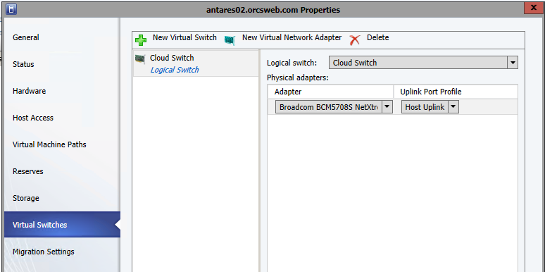
Once the job completes, we’ll be able to associate our Logical Network with our cloud which will allow it to show up in the Service Management Portal. Under VMs and Services > Clouds, right-click on the name of your cloud and select Properties. Click Logical Networks, and select the checkbox next to the name of the Logical Network we created in the first step. Click OK.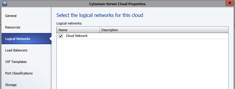
You can now create VM Networks in the Service Management Portal that are bound to the Logical Network using NVGRE.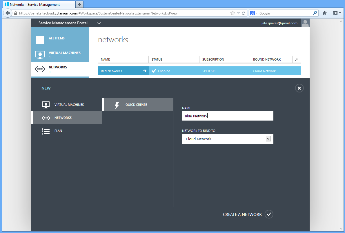
The last step is to create a default VM Network to associate with our templates and hardware profiles. Select VMs and Services > VM Networks and click Create VM Network from the Ribbon. Name the name and associate it with the Logical Network we created in step 1.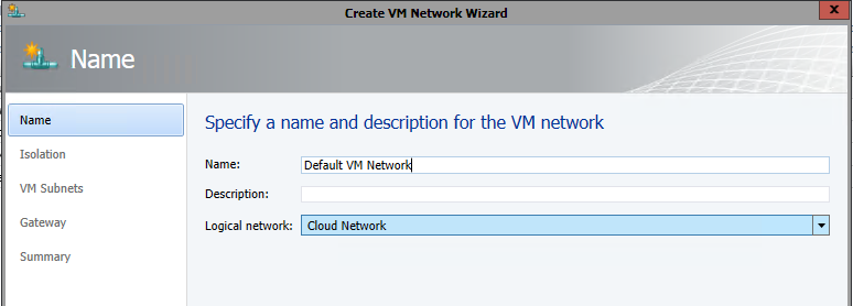
Chose the option to Isolate using Hyper-V network virtualization with IPv4 addresses for VM and logical networks.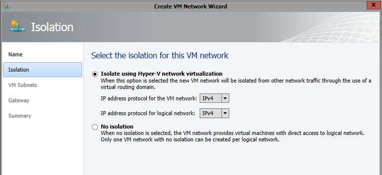
Specify a subnet for VM Network though it will not be used. Select No connectivity on the External connectivity screen and click Finish to create the VM Network. Configure your templates and hardware profiles to use this VM Network in order for them to work properly in the Service Management Portal.